Advertisement
Quick Links
KMT - Kraus Messtechnik GmbH
Gewerbering 9, D-83624 Otterfing, Germany, 08024-48737, Fax. 08024-5532
Home Page: http://www.kmt-telemetry.com, Email: info@kmt-telemetry.com
Multi-channel telemetry system for rotating
application, full software programmable
INSTRUCTIONS FOR QUALIFIED PERSONNEL ONLY!
•
2 to 64 channel
•
Signal bandwidth 0-24000Hz
•
Inputs for STG, TH-K, ICP or VOLT
•
STG - Auto Zero calibration
•
4V bridge Excitation
•
Gain 125-250-500-1000-2000
User Manual
MTP
with 16 bit resolution
•
16 bit ADC, simultaneous sampling
•
Full software programmable
•
Inductive or battery power
•
Rugged housing, water protected
•
Output analog +/- 10V
•
Digital data interface to PC
Advertisement

Summary of Contents for KMT MTP-STG-V3
- Page 1 KMT - Kraus Messtechnik GmbH Gewerbering 9, D-83624 Otterfing, Germany, 08024-48737, Fax. 08024-5532 Home Page: http://www.kmt-telemetry.com, Email: info@kmt-telemetry.com User Manual Multi-channel telemetry system for rotating application, full software programmable with 16 bit resolution INSTRUCTIONS FOR QUALIFIED PERSONNEL ONLY! •...
-
Page 2: Safety Notes
Safety notes • The device should only applied by instructed personnel. • The power head emits strong magnetic radiation at 30-60 kHz to a distance of 300 mm. Therefore persons with cardiac pacemakers should not work with this device! • Magnetic data storage media should be kept in a distance of at least 3m from the power head to avoid data loss. -
Page 3: Short Description
0.1 with inductive telemetry transmission or up to 10m with radio telemetry transmission. Suitable for wireless data transmission rates of 312.5kbit/s up to 5000kbit/s MTP acquisition modules (rotor side) MTP-STG-V3 MTP-VOLT-V3 Acquisition module for 2 strain gages Acquisition module for 2x high level Full, half >=350ohme and quarter... -
Page 4: Data Frame
Signal bandwidth, sampling rates and delay time: Cut off frequency from anti-aliasing filter (-3dB) and sampling rate (red) Delay Time from Analog In to Analog Out (theoretical, brown) Bit rate 2 Channels 4 Channels 8 Channels 16 Channels 32 Channels 64 Channels 24000 Hz max. - Page 5 MTP-DEC8/16/24/32 Receiver unit for max 32 Channels output via 37 pol. Sub D (inductive transmission 45MHz version up to 5000Mbit) Front side view Rear side view Female 37 pole Sub-D for analog signal output, CH 1 to 32 Out of function IND-Pickup head connection (at Power ON LED...
- Page 6 MTP-DEC8/16/24/32 Receiver unit for max 32 Channels output via 37 pol. Sub D (radio transmission version with diversity receiver 312.5-1250kbit) Front side view Rear side view Female 37 pole Sub-D for analog signal output, CH 1 to 32 Out of function! Power Switch HF –Field strength...
- Page 7 MTP-DEC32 Receiver unit for max 32 Channels output via 37 pol. Sub D (radio transmission version with HF BOX Quad with 4 receiver 1250 … 5000kbit) PCM OUT Pin 1 ----- Pin 2 = PCM + (pink wire) Pin 3 = PCM -- (blue wire) 4x HF Level display Pin 4/5 = common GND &...
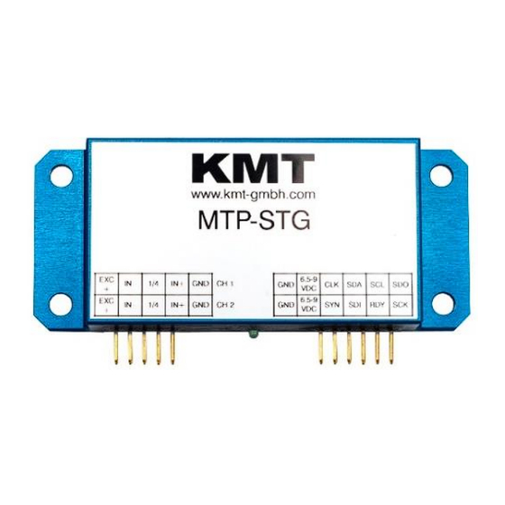
- Page 8 MTP-STG - Acquisition module for 2 channels strain gages (STG) MTP-STG-V3 Acquisition module for 2 strain gages Full, half >=350ohme and quarter bridge 350ohme Fixed excitation 4V DC Offset calibration by auto zero Manual offset shifting after auto zero Gain: 125-250-500-1000-2000...
- Page 9 MTP-VOLT - Acquisition module for 2 channels high level inputs MTP-VOLT-V3 Acquisition module for 2x high level inputs Range: ±0,625V, ± 1,25V, ±2,5V, ± 5V, ±10V Signal bandwidth 0Hz to 24000Hz* (*see table of cut-off-frequency) Add. +4V sensor excitation max. 20mA Resolution 16bit Accuracy <0.2% Powering: 6.5-9V DC...
- Page 10 MTP-ICP - Acquisition module for 2 channels ICP sensor ® MTP-ICP Acquisition module for 2 ICP sensors Current EXC. 4mA Gain: 1-2-4-8-16-32 Signal bandwidth 3 Hz to 24000Hz* (*see table of cut-off-frequency) Resolution 16bit Accuracy <0.2% Powering: 6.5-9V DC Current consumption 100mA Vibration: 5g Static acceleration: 3000g Shock: 10000g...
- Page 11 MTP-Pt100/1000 - Acquisition module for 2 channels RTD sensor MTP-Pt100/1000 (RTD) Acquisition module for 2 RTD sensors Range -100 to 600°C, -50 to 300°C or -25 to 150°C Type Pt100 or Pt1000 Current EXC. 1mA Connection: 4-wire, 3-wire and 2 wire Sensor break detection Signal bandwidth 6Hz Resolution 16bit...
- Page 12 MTP-Pt100 - Temperature range table Temperature measuring range Pt100: -100 to 600°C C Temperature Output Temperature Output Temperature Output Temperature Output [°C] [°C] [°C] [°C] -0.50 1.50 3.50 5.50 0.00 2.00 4.00 6.00 0.50 2.50 4.50 1.00 3.00 5.00 Temperature measuring range Pt100: -50 to 300°C or Temperature Output...
- Page 13 MTP-TH-K - Acquisition module for 2 channels thermo couples MTP-TH-K Acquisition module for 2x TH-K Inputs galvanic isolated Range -50 to 1000°C, -50 to 500°C or -50 to 250°C Cut-off filter 30Hz (standard) more on request Resolution 16bit Accuracy: 0.2% at 1000°C range Powering: 6.5-9V DC Current consumption 110mA with cold junction compensation plate Vibration: 5g...
- Page 14 MTP-TH-K - Temperature range table Temperature measuring range type K: -50°C to +1000°C Temperature Output Temperature Output Temperature Output Temperature Output [°C] [°C] [°C] [°C] -0.50 2.50 5.50 8.50 0.00 3.00 6.00 9.00 0.50 3.50 6.50 9.50 1.00 4.00 7.00 1000 10.00 1.50...
- Page 15 MTP-CONTROLLER - Controller for 1- 32 acquisition modules = 64 channels MTP-CONTROL Controller for 1- 32 acquisition modules = 64 channels Output: PCM Programmable via LAN adapter Powering: 6.5-9V DC Current consumption 40mA (with connected LAN Adapter80mA) Vibration: 5g Static acceleration: 3000g Shock: 10000g Powering and Connection for radio or inductive transmitter...
- Page 16 IND TX - Inductive transmitter MTP-IND-TX (New version 2016) for MTP Inductive data transmission transmitter with 45MHz carrier Transmission rate 2500kbit/s, optional 5000kBit/s Distance up to 100mm, typical 50mm (between coil and pickup) Consumption of current: 70mA Powering: 5V DC (powering comes via MTP-Controller) Vibration: 5g Static acceleration: 3000g Shock: 10000g...
- Page 17 MTP-IND TX - Inductive transmitter - Connection Version 2018-11 Technical Data are subject to change without notice!
- Page 18 Water protected, but not connectors! HF SMA HF LED antenna ON if OK connection Pins are for KMT internal use only! Typical connection Power and data Wire antenna for shaft application with SMA connector MTP-Control with MTP HF-Tx MT32-HF-TX (Version until 2015) for MTP Radio data transmission transmitter Transmission rate 312.5, 625, 1250, 2500 and 5000kbit/s,...
- Page 19 MTP-HF TX - Radio transmitter - Connection Version 2018-11 Technical Data are subject to change without notice!
- Page 20 MTP - Block diagram example for 32 channels Version 2018-11 Technical Data are subject to change without notice!
- Page 21 MTP – 32 CH cable loom and connection Take care with your pin connection if you solder the cable! - Don’t plug any modules if Power is ON!!! First power OFF!! Version 2018-11 Technical Data are subject to change without notice!
- Page 22 MTP – 24 CH cable loom and connection Take care with your pin connection if you solder the cable! - Don’t plug any modules if Power is ON!!! First power OFF!! Version 2018-11 Technical Data are subject to change without notice!
- Page 23 MTP –picture of 24 CH cable loom with 12xMTP-STG modules, IND-HF Tx and IND-PWR Version 2018-11 Technical Data are subject to change without notice!
- Page 24 MTP – 16 CH cable loom and connection Take care with your pin connection if you solder the cable! - Don’t plug any modules if Power is ON!!! First power OFF!! Version 2018-11 Technical Data are subject to change without notice!
- Page 25 MTP –picture of 16 CH cable loom with 6xMTP-STG modules, IND-HF Tx and IND-PWR Version 2018-11 Technical Data are subject to change without notice!
- Page 26 MTP – 8 CH cable loom and connection Take care with your pin connection if you solder the cable! - Don’t plug any modules if Power is ON!!! First power OFF!! Version 2018-11 Technical Data are subject to change without notice!
- Page 27 MTP – 4 CH cable loom and connection Take care with your pin connection if you solder the cable! - Don’t plug any modules if Power is ON!!! First power OFF!! Version 2018-11 Technical Data are subject to change without notice!
- Page 28 MTP- Explanation of abbreviations of block diagram NSYNC+ : ADC synchronizing signal+ NSYNC- : ADC synchronizing signal- ADCLK+ : ADC clock signal+ ADCLK- : ADC clock signal- SCLK+ : ADC data shift out clock signal+ SCLK- : ADC data shift out clock signal- SCL : IIC clock signal for setting up analog channel parameter SDA :...
- Page 29 MTP acquisition module - dimensions Weight about 60 grams Version 2018-11 Technical Data are subject to change without notice!
- Page 30 Inductive transmission (2500kbit) with MTP-IND-TX-RX with 45MHz carrier! With 45MHz carrier is only 1x winding necessary! Attach for electromagnetic insulation “Ferrite Tape” 2 x one layer around the shaft. Strip the isolation from the end of the wire with a skinning tool or head up you soldering iron over 450°C to burn off the insulation from the wire!
- Page 31 MTP-IND-TX-RX with 45MHz carrier! Pickup head (2500kbit) Inductive Pick-Up head mount in this position! Distance between head and Tx coil can be up to 100mm Typical 50mm, distance deepens of application!! To avoid transmitting problems, the transmitter module must be close the transmitting antenna! The cables (PCM/GND/+5V) between MPT-IND-TX 45MHz and MTP-CONTROL can be 1000mm long! CAUTION: If you want to install also an inductive power coil close to the data coil, the minimal distance must be <10mm!
- Page 32 Picture of IND-PICKUP-HEAD 45MHz Version 2018-11 Technical Data are subject to change without notice!
- Page 33 Dimensions of IND-PICKUP-HEAD 45MHz Version 2018-11 Technical Data are subject to change without notice!
- Page 34 MTP 312.5 - 5000k Installation of the radio transmitter on a shaft For rotating application we normal recommend an inductive transmission instead of radio transmission! Cable Red = +5V Cable Black = GND (Ground) Cable Brown = PCM In Cable White = Wire antenna All cable connections should be soldered.
- Page 35 Software setup via LAN-Adapter and notebook Power IN 6.5-9V DC LAN Adapter e.g. IP: 192.168.0.110 (see current IP no. on LAN-Adapter!!) 1) Power the MTP modules with power 6.5-9VDC 2) Connect the LAN-Adapter with the MTP-CONTROL module (see pin connection at MTP-CONTROL) 3) Adjust your notebook to manual on e.g.
- Page 36 MTP-CONTROL V3 - Software setup DOWNLOAD parameters for device First you can download the stored parameters from the acquisition modules via LAN adapter from the controller module . All connected acquisition modules will detect! Caution: Never use the refresh button on your browser;...
- Page 37 BRIDGE setting STG Select full-, half- or quarter-bridge by popup window “Upload Parameters to MT-PRO and perform Autozero” Execute through button If you want test your bridge, you can execute the function Test-Shunt Resistor for 20 sec. button In this case all STG channels get a shunt-cal step of about 80% of the from measuring range at GAIN 2000 In this case all STG channels get a shunt-cal step of about 40% of the from measuring range at GAIN 1000 In this case all STG channels get a shunt-cal step of about 20% of the from measuring range at GAIN 500 In this case all STG channels get a shunt-cal step of about 10% of the from measuring range at GAIN 250...
- Page 38 GAIN setting STG Select gain of 125-250-500-1000 or 2000 by popup window After change the gain you must make a new autozero!! “Upload Parameters to MT-PRO and perform Autozero” Execute through button Version 2018-11 Technical Data are subject to change without notice!
- Page 39 AutoZero setting STG Select Auto-Zero per channel. The Auto-Zero function will be executed only one time per upload the parameters to MTP-STG! It will be stored also after power off in the MTP-STG until you make a new Auto-Zero on this channel! “Upload Parameters to MT-PRO and perform Autozero”...
- Page 40 Manual Offset shifting after AutoZero After AutoZero you can shift (if necessary) the offset in +/-2000 steps “Upload Parameters to MT-PRO and perform Autozero” Execute through button Version 2018-11 Technical Data are subject to change without notice!
- Page 41 KMT - Kraus Messtechnik GmbH Gewerbering 9, D-83624 Otterfing, Germany, 08024-48737, Fax. 08024-5532 Home Page: http://www.kmt-telemetry.com, Email: info@kmt-telemetry.com Konformitätserklärung Declaration of Conformity Declaration de Conformité KMT - Kraus Messtechnik GmbH Nous Anschrift Gewerbering 9, D-83624 Otterfing, Germany Address Adress erklären in alleiniger Verantwortung, daß...
- Page 42 KMT - Kraus Messtechnik GmbH Gewerbering 9, D-83624 Otterfing, Germany, 08024-48737, Fax. 08024-5532 Home Page: http://www.kmt-telemetry.com, Email: info@kmt-telemetry.com INDUCTIVE POWER XL, XXL and XXXL with flat COIL User Manual Inductive power supply set Power supply for power head 25 and 50mm mounting tape Ferrite tape CUL 1.00 mm...
- Page 43 Safety notes for inductive powering • The device should only applied by instructed personnel. • The power head emits strong magnetic radiation at 30-60 kHz to a distance of 300 mm. Therefore persons with cardiac pacemakers should not work with this device! •...
- Page 44 MTP-IND-PWR - AC/DC Module for inductive OLD power V01…03 = version until 9/2015 MTP-IND-PWR (V01..03) AC/DC Module for inductive power Input: 30-60kHz 10-60V AC Can also power with DC 24V (Input on COIL / COIL) Output: 6.5 DC Current: up to 2400mA Weight: 60 gram Vibration: 5g Shock: 3000g...
- Page 45 MTP-IND-PWR - AC/DC Module for inductive power NEW version from 9/2015 MTP-IND-PWR (V04….) AC/DC Module for inductive power Input: 30-60kHz 10-60V AC Can also be power with DC 24V (Input on AC1 / AC2) Output: 6.5 DC Current: up to 2400mA Weight: 60 gram Vibration: 5g Shock: 3000g...
- Page 46 MTP-IND-PWR - AC/DC Module for inductive power (new version from 9/2015 …) connection diagram Version 2018-11 Technical Data are subject to change without notice!
- Page 47 MTP module housing - dimensions Weight about 60 grams Version 2018-11 Technical Data are subject to change without notice!
- Page 48 MTP-inductive power supply Installation of coil for inductive powering on shaft Attach for electromagnetic isolation “Ferrite Tape” 2x parallel and 1x in the middle over two layer around the shaft Strip the isolation from the end of the wire with a skinning tool or head up you soldering iron over 450°C to burn off the insulation from the wire!
- Page 49 Solder the end of the wire on the AC IN of the Fixed with 3 layers mounting tape IND-PWR module and isolate all solder points with shrink tubing. Note: “The inductive load of the MTP- IND-PWR and the capacitor in the Power Head must be in resonance to get the optimal transmission.
- Page 50 Find the correct amount of windings of inductive power coil Optimum windings for steel shafts 1200 1000 Windings Missing turns occasionally can be compensated by increasing the tuning capacity from 150nF up to 470nF Windings Diameter (+/-1) (mm) 4 250nF 1000 5 150nF 6 150nF...
- Page 51 Recommend power heads: Diameter: 150mm 300mm 500mm 1000mm 4 - Channel 8 - Channel XXXL 16 - Channel XXXL XXXL 32 - Channel XXXL XXXL On request IND-PWR-HEAD-XL and XXL IND-PWR-HEAD-XXXL Caution for use of XXL and XXXL power heads! Cable must unrolled for use, otherwise it will warm up! Version 2018-11 Technical Data are subject to change without notice!
- Page 52 Dimensions of IND-PWR-HEAD- XL and XXL Version 2018-11 Technical Data are subject to change without notice!
- Page 53 Dimensions of IND-PWR-HEAD-XXXL Version 2018-11 Technical Data are subject to change without notice!
- Page 54 MTP-IND-PWR Following must be considered at the mounting of the inductive power head Shaft with Cu wire Coil 25-30mm Magnetic field Don’t use for mounting any kind metal in this area (25-30mm)! Otherwise magnetic energy will flow in the metal and decrease the distance between Example of mounting power head and coil (on shaft)!
- Page 55 IND-Power generator for L, XL, XXL and XXXL Powerhead Technical data Power output: AC 25-35kHz for power head L, XL, XXL and XXXL Power input: 10-30 V DC, typical 24V Power consumption <100 Watt, deepens of power head Dimensions: 205 x 105 x 65mm Weight: 1.275 kg Environmental...
-
Page 56: Pin Connection
MTP-IND-PWR-XXL Pin connection CONTROL - Not used! DC 10-30V AC 25-35kHz output power head typical 24V (up to 100 WATT* * deepens of power head) E= have no function Powering and AC out LED flashing = auto adjustment LED ON = finish ON= Inductive resonance freq. - Page 57 KMT - Kraus Messtechnik GmbH Gewerbering 9, D-83624 Otterfing, Germany, 08024-48737, Fax. 08024-5532 Home Page http://www.kmt-telemetry.com, Email: info@kmt-telemetry.com INDUCTIVE POWER with RING COIL User Manual Inductive power supply set AC/DC Adapter Power supply Inductive Power Head with 5m cable...
- Page 58 Safety notes for inductive powering • The device should only applied by instructed personnel. • The power head emits strong magnetic radiation at 30-60 kHz to a distance of 300 mm. Therefore persons with cardiac pacemakers should not work with this device! •...
- Page 59 MTP-IND-PWR - AC/DC Module for inductive power V01…03 = version until 9/2015 MTP-IND-PWR AC/DC Module for inductive power Input: 30-60kHz 10-60V AC Can also be power with DC 12-24V (Input on COIL / COIL) Output: 6.5 DC Current: up to 2400mA Weight: 60 gram Vibration: 5g Shock: 3000g...
- Page 60 MTP-IND-PWR - AC/DC Module for inductive power (new version from 9/2015 …) MTP-IND-PWR (V04….) AC/DC Module for inductive power Input: 30-60kHz 10-60V AC Can also be power with DC 24V (Input on AC1 / AC2) Output: 6.5 DC Current: up to 2400mA Weight: 60 gram Vibration: 5g Shock: 3000g...
- Page 61 MTP-IND-PWR - AC/DC Module for inductive power (new version from 9/2015 …) connection diagram Version 2018-11 Technical Data are subject to change without notice!
- Page 62 MTP-IND-PWR housing - dimensions Weight about 60 grams Version 2018-11 Technical Data are subject to change without notice!
- Page 63 Inductive power supply RING COIL - Distance power head and pickup head Solder pins for power coil and wire to IND-PWR 6.5V Please use twisted wire (must not shield!) IND-Data Pickup Distance to coil IND-PWR Head typical 5-50mm Distance to coil In ideal case upto 100mm 5-30 mm CUL 0.63 mm for IND-DATA...
- Page 64 Use a ferrite core and make 2 loops with the twisted pair cable through the core! Normal is this ferrite core a part of the delivery at RING Coil version from KMT!! At new version IND-PWR V04 not more necessary...
- Page 65 Inductive power supply RING COIL – wire connection We recommend to fix the wire of coil with some epoxy resin (data & power coil) Use shrink tubing Direct behind the solder pins the data wire must be twisted, otherwise you can get data transmission problems! Best use shield twisted pair cable or cover wire with aluminum foil...
- Page 66 Inductive power supply RING COIL – Distance power head PWR-COIL DATA-COIL 5 winding with 1 winding with CUL wire 0.63mm CUL wire 0.63mm (Enamelled copper wire) (Enamelled copper wire) Windings depends of diameter!! See label on RING Coil Distance 5-30mm Distance +/-9mm Version 2018-11...
- Page 67 Inductive power supply Example of a RING COIL with inner diameter 191mm Version 2018-11 Technical Data are subject to change without notice!
- Page 68 Dimensions of IND-PWR-HEAD-XXL Version 2018-11 Technical Data are subject to change without notice!
- Page 69 Dimensions of IND-PWR-HEAD-XXL Version 2018-11 Technical Data are subject to change without notice!
- Page 70 IND-PWR-HEAD-XXL Caution for use of power heads! Cable must unrolled for use, otherwise it will warm up! Version 2018-11 Technical Data are subject to change without notice!
- Page 71 Dimensions of IND-PWR-HEAD-XXXL Version 2018-11 Technical Data are subject to change without notice!
- Page 72 IND-PWR-HEAD-XXXL Caution for use of power heads! Cable must unrolled for use, otherwise it will warm up! Version 2018-11 Technical Data are subject to change without notice!
Need help?
Do you have a question about the MTP-STG-V3 and is the answer not in the manual?
Questions and answers