Table of Contents
Advertisement
Quick Links
Advertisement
Table of Contents

Related Manuals for Sealite SL-PEL-05

Summary of Contents for Sealite SL-PEL-05
- Page 1 SL-PEL Series Sectored Port Entry Light Installation & Software Guide Version 2.6...
- Page 2 5o SL-PEL-05 Model Model 5° SL-PEL-05 1272 16mm wide Slotted Holes Diam 235mm Slotted Holes on PCD 200mm MOUNT PLATE 1 MOUNT PLATE 2 Model 10° SL-PEL-10 10o SL-PEL-10 Model Slotted Holes on PCD 200mm Diam 235mm BASE (Hole Pattern) Version No. Description Date Author Approved Manual Launch March 2014 D. Tomaszewicz Quick Start Guide April 2014 D.
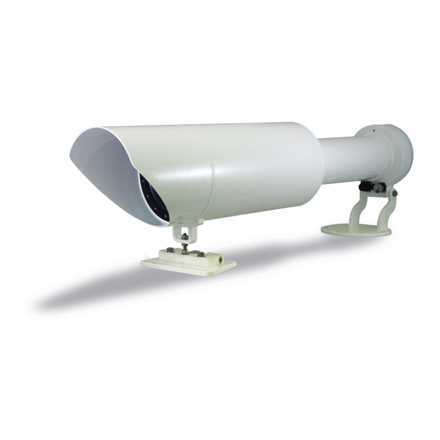
- Page 3 The Sealite Port Entry Light (PEL) is a low-powered, high-intensity precision sector light, suitable for day or night-time use. Providing over 120,000cd (10o Model) and 500,000cd (5o Model) at 30 watts, the Sealite PEL is extraordinarily efficient and ideal for solar power systems. The light is designed to suit high- precision sector applications and provides a measured changeover between colour sectors of typically one minute of arc.
- Page 4 SL-PEL Series Sectored Port Entry Light QUICK START GUIDE For full Installation Guide see page 10. Load USB SW onto Computer Connect power cable to PEL...
- Page 5 SL-PEL Series Sectored Port Entry Light Connect power cable to a Power Supply set to 12.5V / 3A: If you’ve purchased a power supply, simply connect to mains. If you’ve purchased a standalone unit, the power connections are: Label Colour Connect to: BATTERY + 12.5V +...
-
Page 6: Table Of Contents
Operation Mode tab ................Page 24 Operation Mode Settings ................Page 24 Factory Reset ....................Page 25 Intensity tab ..................Page 26 Adjusting Intensities ..................Page 26 Viewing Adjusted Intensities ................ Page 27 Latest products and information available at www.sealite.com... - Page 7 Optional GSM Cell Phone Monitoring & Control ......Page 52 Maintenance and Servicing ............. Page 53 Trouble shooting ................Page 54 PEL Warranty Statement ..............Page 54 Sealite LED Light Warranty ............. Page 55 Latest products and information available at www.sealite.com...
-
Page 8: Introduction
Precision Construction Commitment to investing in the design and construction of injection-moulded parts including optic lenses, light bases and a range of other components ensures that all Sealite products are of a consistent & superior quality. Optical Performance Sealite manufactures a range of marine LED lenses moulded from multi-cavity dies. The company has superior in-house lens manufacturing capabilities to support outstanding optical performance. -
Page 9: Sl-Pel Series
• AIS Type 1 or Type 3 • GSM Remote Monitoring & Control • GSM Remote Monitoring & Control Capabilities Capabilities • GPS Synchronisation • GPS Synchronisation • Variety of solar/battery configurations • Variety of solar/battery configurations Latest products and information available at www.sealite.com... -
Page 10: Installation Guide
50% equates to the tallest bridge height on the largest tide. The reverse is true for the smallest vessel on the lowest tide and the point of exit. Sealite engineers can offer advice in this regard upon request. -
Page 11: Improving Traditional Leads With A Pel
The “series of pictures” method can be extended to include approach to the bearing line noting beacons and buoys used in the passage of which further mention will be made later in this manual. Latest products and information available at www.sealite.com... -
Page 12: Night-Time Use
It is recommended that during the project’s engineering stage that a series of pictures are taken of the ship’s view during approach during the time of a rising or setting sun, or any other harsh conditions to make a valid assessment of light intensity required. Sealite engineers may also be consulted for their recommendations. -
Page 13: Supporting Aids
Through a combination of suitability and cost implications a theoretical position can be determined and proposed to define safe passage through the channel and any obstacles. This latitude and longitude point should be recorded and filled into the Sealite PEL Information Checklist and sent to Sealite to aid discussions. -
Page 14: Alignment Of The Pel Sector Light
(if used to get to the location). Personnel required At the reference point: One competent observer with VHF radio or mobile phone who can communicate in the same language as the commissioning technician without the need of a translator. Latest products and information available at www.sealite.com... - Page 15 300 mm. 8. When the technician and acceptance officer are satisfied, the light may be tightened into position. Latest products and information available at www.sealite.com...
- Page 16 This should be performed by adjusting the adjustment screw beneath the barrel and locked as pictured. A small spirit level placed on the barrel will assist. Latest products and information available at www.sealite.com...
-
Page 17: Final Sea Check
If it is an omnidirectional light of a different colour intended to be seen separately from the sector, it should be positioned (ideally) on the centre line, or at least between 3 and 6 metres below the sector depending on range. Latest products and information available at www.sealite.com... -
Page 18: Care And Handling Of The Pel
Goods should bot be signed for without unpacking and checking for damage - Retain Sealite packing for safe transportation of the PEL to the tower. - Never place hard or rough surfaces on PEL optics as the lens can be easily scratched and chipped. -
Page 19: Software Guide
SOFTWARE GUIDE USB interface setup 1. Load the Sealite programme to your PC from the memory stick provided. Save the PEL Configuration program and all associated drivers (.dll files) onto a local drive. 2. Connect the USB cable between the PEL USB port and the test PC as shown below:... - Page 20 ALL -ve BLACK VBATT +ve PAIR VBATT -ve BLUE 4. Open the PEL Configuration tool on the PC (.exe file). 5. Choose “COM Setup” from the menu at the top of the screen. Latest products and information available at www.sealite.com...
- Page 21 7. With the com port selected, set the baud rate to 9600 and press the OK button. Note: If COM port fails to connect, please refer to the ‘Trouble Shooting’ section of this manual. Latest products and information available at www.sealite.com...
-
Page 22: Info Tab
This orientation is selected at the time of order and is dependent on whether the Unit will be used in an IALA Buoyage System A (rest of the World) area or Buoyage System B (Americas and Japan). (Note: The flashing character is representational only and NOT the programmed code of the unit.) Latest products and information available at www.sealite.com... -
Page 23: Event Log
NOTE: there is an option to interconnect a standard GSM monitor which will provide the service engineer with a TEXT message to direct his mobile and/or Sealite Internet based global hub. Further details can be found in the GSM User Manual. -
Page 24: Operation Mode Tab
*Note: When testing these functionalities, masking the internal light sensor or shining bright light might be necessary depending on light conditions. The internal light sensor is located on the top of the PEL as shown below. Internal light sensor Latest products and information available at www.sealite.com... -
Page 25: Factory Reset
Flash Code: 000; and varying intensities based on LED Colours. CAUTION: Resetting to Factory Default Settings will not restore custom settings. For details on custom settings, refer to the PEL Checklist shipped with your PEL. Latest products and information available at www.sealite.com... -
Page 26: Intensity Tab
Modulation (PWM) duty cycle value in percentage format. When entering a value in candela format, the percentage will automatically be calculated and displayed. Once a value is entered, select any ‘Write’ button in the Intensity tab, and the intensities will change. Latest products and information available at www.sealite.com... -
Page 27: Viewing Adjusted Intensities
Note: The percentage value shown in the Lantern Information area may be slightly higher than what was entered due to software rounding. As is shown below, an intensity of 4% is written, but an intensity of 6.25% is read. Latest products and information available at www.sealite.com... -
Page 28: Flash Code Tab
Flash Code tab The PEL can be setup to use any of the standard (0x00 to 0xFF) and extended (0x100 to 0x130) Sealite flash codes. Each LED in the PEL can be setup to use a different flash code using either the Flash Code Tab or the Advanced Tab (explained later). -
Page 29: Custom Flash Codes
FIXED FIXED Uniform Intensity Across All Colours • SL-PEL-10 • Flashing boundary effect with no moving parts • Full intensity across all sectors • Automatic night dimming via PE cell (no moving lters) Latest products and information available at www.sealite.com... -
Page 30: Sensor Tab
Low Battery Threshold (Default: 11.5V) • OK Threshold (Default: 12.0V) In addition, the Battery Sensor displays: • The current Supply Voltage • The factory default voltage settings Low Battery Voltage Options (Default: All Enabled) • Latest products and information available at www.sealite.com... -
Page 31: Changing Battery Thresholds
12.0V the light will return to normal operation. NOTE: Remember to check the current operation mode as the PEL may require a certain light level to return to expected intensity. SEALITE DOES NOT RECOMMEND ADJUSTING BATTERY THRESHOLDS Latest products and information available at www.sealite.com... -
Page 32: Temperature Sensor
Changing Temperature Thresholds Identify temperatures to be changed. Type the new temperatures below the current temperature settings and click ‘Write.’ The temperature threshold settings will change. SEALITE DOES NOT RECOMMEND ADJUSTING TEMPERATURE THRESHOLDS Latest products and information available at www.sealite.com... -
Page 33: Disabling/Enabling Temperature Threshold Options
To disable any functionality, ensure the box to the left of the option is unchecked and click ‘Write.’ Options disabled To enable any functionality, ensure the box to the left of the option is checked and click ‘Write.’ Options enabled Latest products and information available at www.sealite.com... -
Page 34: Led Sensor (Led Diagnostics)
Zero intensity. This is discussed further in the Advanced Tab section. Disabling/Enabling Alarm Options To disable the alarm relay, ensure the box to the left of the option is unchecked and click ‘Write.’ Options disabled Latest products and information available at www.sealite.com... - Page 35 SL-PEL Series Sectored Port Entry Light To enable the alarm relay, ensure the box to the left of the option is checked and click ‘Write.’ Options enabled Latest products and information available at www.sealite.com...
-
Page 36: Light Sensor
Sealite recommends using the default settings when commissioning the PEL. If it is desired that the sector PEL should switch on at same time as a buoyed channel then the site should be revisited. Use the PEL as a photometer to read the value under the “Current Level”... -
Page 37: Managing Light Sensor Thresholds
Identify light thresholds to be changed. Type the new thresholds below the current Lux settings and click ‘Write.’ The Lux threshold settings will change. Note: If the light sensor is not enabled, changes to the settings may not be made. Latest products and information available at www.sealite.com... -
Page 38: Advanced Tab
Mode, Intensities and Flash Settings. LANTERN INFORMATION This area displays: • LED Colour Configurations • Night-time and Daytime Intensity Settings (Percentage) • Flash Code Settings (Hex) • Sync Offset (sec) • Operation Mode Latest products and information available at www.sealite.com... -
Page 39: Lantern Setup
SL-PEL Series Sectored Port Entry Light LANTERN SETUP Latest products and information available at www.sealite.com... -
Page 40: Intensity
Dusk till Dawn - only night intensities can be set • Day and Night - both night and day intensities can be set • Standby – neither night nor day intensities can be set Latest products and information available at www.sealite.com... -
Page 41: Flashcode
Writing LED Synchronisation Sync Offset settings for each individual LED may be entered in the Sync Offset Column (in seconds, Max Offset=5.1s). Enter the Sync Offset for each LED and click ‘Write Sync.’ Latest products and information available at www.sealite.com... -
Page 42: Ais Tab
SL-PEL Series Sectored Port Entry Light AIS Report tab For users with AIS enabled, the Sealite AIS message is sent from the PEL on the serial port every 10 seconds. This message contains • Product name (PEL) • Lantern status information... -
Page 43: Gps Synchronisation
The PEL is user-programmable to set each LED to a different flash code. Currently the GPS synchronisation system can only synchronise one flash code at a time. The steady on flash code does not require synchronisation. Synchronisation will occur Latest products and information available at www.sealite.com... - Page 44 Synchronisation will not occur Under harsh environmental conditions the GPS data may not be available. If a loss of GPS data is encountered the lantern should keep its GPS active until the problem is rectified. Latest products and information available at www.sealite.com...
-
Page 45: Examples Of Pel Beam Configurations
• Synchronised LEDs are programmable in both intensity and character • Length of beam indicates intensity • Illustration shows SL-PEL-10 with 10 x 1º sectors • The SL-PEL-05 variant produces 10 x 0.5º sectors Range of SL-PEL-10 @ T=0.74 at night See Reference Guide ‘Daytime Range of Signal Lights’... -
Page 46: Flash Codes
Sectored Port Entry Light Flash Codes Sealite marine lanterns may be set to any of IALA recommended flash settings. These can be set via rotary switches inside the lantern or the IR remote or via the Sealite Configuration Tool. SEALITE® code reference is listed by number of flashes For the latest version of this document visit www.sealite.com... - Page 47 FL 5 S FL 15 S 14.0 FL 5 S LFL 15 S 11.0 FL 5 S OC 15 S FL 5 S LFL 20 S 18.0 FL 26 S 25.0 FL 5 S Latest products and information available at www.sealite.com...
- Page 48 FL (2) 12 S 10.0 FL (2) 12 S FL (2) 15 S 11.0 FL (2) 15 S 11.0 Q (2) 15 S 13.8 FL (2) 20 S 15.0 FL (2) 25 S 22.0 Latest products and information available at www.sealite.com...
- Page 49 VQ (3) 15 S 13.7 FL (2) + LFL 16 S FL (3) 20 S 12.5 FL (3) 20 S 15.5 FL (3) 20 S 12.0 FL (3) 20 S 15.2 FL (3) 20 S 15.0 Latest products and information available at www.sealite.com...
- Page 50 FL (4) 20 S 13.5 FL (4) 20 S 10.5 FL (4) 20 S Q (4) 20 S 16.5 FL (4) 20 S 12.0 Q (4) 28 S 24.5 FL (4) 30 S 26.5 Latest products and information available at www.sealite.com...
- Page 51 MO (A) 10 S MO (D) 10 S MO (A) 15 S 11.0 MO (U) 15 S 11.8 MO (U) 15 S 10.7 MO (U) 15 S 10.1 MO (B) 15 S 10.5 Latest products and information available at www.sealite.com...
-
Page 52: Optional Gsm Cell Phone Monitoring & Control
Sectored Port Entry Light Optional GSM Cell-Phone Monitoring & Control The Sealite PEL is avialable with GSM monitoring facilities enabling users to access real-time diagnostics data and change lantern settings via cell-phone. The system can also be configured to send out alarm SMS text messages to designated cellular telephone numbers. -
Page 53: Maintenance And Servicing
The Sealite PEL is an LED light source and as a result does not require visits for re-lamping. If fitted with GSM or AIS monitoring the service technician will already have advance notice on the requirement for a visit. -
Page 54: Trouble Shooting
Trouble Shooting Problem Remedy Unable to communicate with 1. Connect the USB drive provided by Sealite and open to view files. PEL via USB 2. Double-click on folder: PELConfigx.xx (note, version number may vary) 3. Double-click on folder: USBDriversForWindows 4. Double-click on folder: Executable 5. -
Page 55: Pel Warranty Statement
No responsibility is taken by Sealite for aligning the PEL unless contracted to do so. If contracted to align, no responsibility will be taken for verification that the channel is free of obstructions. - Page 56 Please complete the Online Registration Form at: www.sealite.com Sealite Pty Ltd will repair or replace your LED light in the event of electronic failure for a period of up to three years from the date of purchase, as per the terms & conditions below.
- Page 57 To the extent permitted by acts and regulations applicable in the country of manufacture, the liability of Sealite Pty Ltd under this Warranty will be, at the option of Sealite Pty Ltd, limited to either the replacement or repair of any defective product covered by this Warranty.
- Page 58 Sealite United Kingdom Ltd Sealite USA LLC Australia Singapore t: +61 (0)3 5977 6128 t: +65 6829 2243 t: +44 (0) 1502 588026 t: +1 (603) 737 1311 Latest products and information available at www.sealite.com sealite.com info@sealite.com We believe technology improves navigation™...
Need help?
Do you have a question about the SL-PEL-05 and is the answer not in the manual?
Questions and answers