Table of Contents
Advertisement
Quick Links
Advertisement
Table of Contents

Subscribe to Our Youtube Channel
Related Manuals for Avidyne DFC100

Summary of Contents for Avidyne DFC100
- Page 3 Page Chg Page Chg Page Chg Cover…...0 2-3……….1 4-8…….…0 Page #..1 2-4……….0 4-9……….0 TOC-1..1 3-1……….0 4-10……..0 TOC-2.…..1 3-2……….0 4-11……..1 1-1……….1 3-3……….1 4-12……..1 1-2……….0 3-4……….0 5-1……….0 1-3……….1 3-5……….0 5-2……….1 1-4……..1 3-6……….0 5-3……….1 1-5……..1 3-7……….0 5-4……….0 1-6…….…1 3-8……….0 5-5……….1 1-7…….…1 3-9……….1 5-6……….1 1-8…….…1 3-10……..0 5-7……….1...
-
Page 4: Table Of Contents
DFC100 Digital Autopilot | PILOT GUIDE TABLE OF CONTENTS System Overview ..............1-2 FUNCTIONAL OVERVIEW ............1-3 GENERAL AUTOPILOT OPERATIONS ........1-4 Basic Autopilot Operation ..............1-4 Capture And Hold Operation ..............1-4 Target (Bug) Setting ................1-4 Aural Alerts ................... 1-5 Armed vs Engaged Mode Indications ............ 1-6 Mode Transition Indication .............. - Page 5 ILS approach including glide slope intercept ......... 4-7 Procedure Turn ILS or Localizers ............4-8 Back course approaches ............... 4-9 Missed Approach ................4-10 Take off/Go Around (TO/GA) Mode ............. 4-11 Abnormal Procedures ............5-2 GENERAL FAILURE MODE INFORMATION .......5-2 OTHER ERROR MODES .............5-5 ALERTS ..................5-7 LOSS OF ENGINE ..............5-10 Limitations and Performance ..........6-2...
- Page 7 System Overview ..............1-2 FUNCTIONAL OVERVIEW ............1-3 GENERAL AUTOPILOT OPERATIONS ........1-4 Basic Autopilot Operation ..............1-4 Capture And Hold Operation ..............1-4 Target (Bug) Setting ................1-4 Aural Alerts ................... 1-5 Armed vs Engaged Mode Indications ............ 1-6 Mode Transition Indication ..............1-6 Manual Electric Trim Disconnect ............
-
Page 8: System Overview
DFC100 that pilots give careful attention to the material contained within these NOTEs. Boxed areas marked as... -
Page 9: Functional Overview
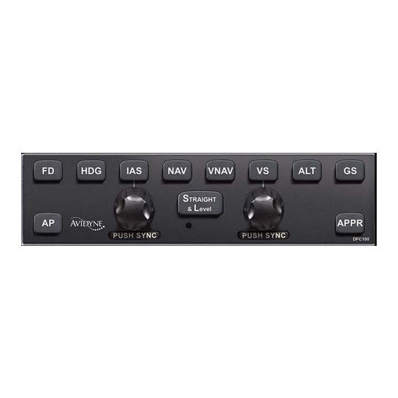
FUNCTIONAL OVERVIEW The Avidyne DFC100 autopilot supports the following functions: • Flight Director • Heading Capture/Hold • NAV Tracking • Vectors Mode • VNAV Tracking • Approach Mode (includes LOC, ILS, VOR, BC, LPV, LNAV/VNAV, LNAV+V) • Altitude Hold • Altitude Capture •... -
Page 10: General Autopilot Operations
BASIC AUTOPILOT OPERATION The DFC100 autopilot always has both a lateral and vertical mode active when engaged. If a specific lateral mode has not been selected by the pilot, then the system defaults to Roll Hold mode. -
Page 11: Aural Alerts
AURAL ALERTS Aural alerting, through the aircraft intercom system, is provided for warnings from the autopilot. In the context of the bullets below, “coupled” describes the condition when the autopilot servos are flying the airplane and “non-coupled” describes the condition when the servos are not flying the airplane and instead, the pilot is expected to follow the flight director command bars. -
Page 12: Armed Vs Engaged Mode Indications
ARMED VS ENGAGED MODE INDICATIONS The DFC100 autopilot has more readily distinguishable armed vs. engaged modes in order to provide the user higher awareness of the current autopilot state and upcoming state transitions. An armed mode is defined as a state that will be captured when and if the airplane crosses that target. -
Page 13: Manual Electric Trim Disconnect
panel and mode annunciation on the PFD changing to green and flashing for up to 10 seconds. Note that the engaged (green) autopilot mode annunciators will also flash when in underspeed or overspeed conditions. This flashing is intended to gain the pilot’s attention and to indicate that while the modes are still engaged (green), the underspeed or overspeed condition may be affecting the system’s ability to hold the target value. -
Page 14: Envelope Protection
ENVELOPE PROTECTION The DFC100 system provides speed-based Envelope Protection (underspeed and overspeed warnings and protection) when in any coupled autopilot mode. NOTE No Envelope Protection in Flight Director Mode Envelope Protection is not provided during flight director-only (non-coupled) operations. NOTE... -
Page 15: Full-Time Envelope Alerting
, changes depending on flap position. NOTE Envelope Protection During Icing Conditions The DFC100 autopilot is not to be used during icing conditions in any non-FIKI approved aircraft, or during severe icing conditions in any FIKI approved aircraft. The autopilot does not have any kind of AOA or icing input and therefore does not register changing aircraft dynamics during icing conditions. - Page 16 Full-time Envelope Alerting is triggered when the DFC100 recognizes an underspeed, overspeed or excessive bank angle condition and will alert the pilot via text alerts on the PFD pages and aural alerts. NOTE Suppression of Full-time Envelope Alerting Full-time Envelope Alerting is suppressed during...
- Page 17 If the autopilot is not engaged in any Autopilot or Flight Director modes and is in the standby condition, as indicated by the green “AP READY” annunciator on the PFD and no green or cyan lights on the autopilot control head, Full-time Envelope Alerting is still active.
-
Page 18: Barometer Setting Adjustment
Finally, if at any time and in any flight director or standby state, the system detects an excessive bank condition, a “BANK LIMIT” text alert is displayed along the top edge of the PFD pages and a “CAUTION, EXCESSIVE BANK” aural alert is played in the headsets and is repeated approximately every 6 seconds until the condition is no longer valid. -
Page 19: Engagement And Hold Limits
ENGAGEMENT AND HOLD LIMITS The DFC100 has maximum engagement limits beyond which the autopilot may not allow a mode to be selected, and maximum hold limits for various parameters. The engagement limits of the autopilot are wider than the hold limits. If the autopilot is engaged... -
Page 20: Comparators
COMPARATORS There are various comparators running in the IFD and DFC100 system as noted in the chart below. If conflicting information is provided, the comparator identifying the conflict with the accompanying pilot indication and autopilot behavior is noted in the table below:... -
Page 21: Autopilot Engagement
DFC100 (except GS and APPR) will engage the autopilot. If a specific lateral and/or vertical mode is not pressed, the DFC100 will default to ROLL hold mode in the lateral channel and PITCH hold mode in the vertical channel. -
Page 22: Fd Vs. Ap
Press the “AP” button on the autopilot control panel (servos will disconnect but the flight director will remain active); Pull the circuit breaker(s) controlling the power to the autopilot. For those aircraft with the stall warning wired directly to the autopilot, the autopilot will disconnect if the aircraft stall warning alarm is triggered. -
Page 23: Pfd Annunciations
The flight director command bars in a DFC100 autopilot are designed for easy use and improved performance during uncoupled autopilot operations. During coupled operations (both “AP” and “FD” buttons lit), pressing the “FD” button will have no effect. Pressing the “AP”... - Page 25 Normal Startup Sequence ..........2-2 POWER CONSIDERATIONS ............2-2 SELF-TEST/ALIGNMENT ............2-2 BRIGHTNESS CONTROLS ............2-2 PRE-FLIGHT TEST ..............2-3 BEFORE TAKEOFF TECHNIQUES ..........2-4 Normal Startup Sequence...
-
Page 26: Normal Startup Sequence
The DFC100 consumes 0.25A when no servos are in operation and up to 0.9A with all servos operating at 100% duty cycle. There is no on/off switch for the DFC100. As soon as the power bus is active through normal aircraft checklist steps, the autopilot will power up. -
Page 27: Pre-Flight Test
PRE-FLIGHT TEST 1. Ensure “AP READY” is displayed on PFD annunciator strip 2. Press AP button on autopilot control head a. Ensure AP button is lit in green b. Ensure “AP”, “ROLL”, “PITCH” annunciations are depicted in green on the PFD annunciator strip and “ALT”... -
Page 28: Before Takeoff Techniques
NOTE Preflight Test Does Not Test Every Aspect of AP The Pre-Flight test of the DFC100 autopilot outlined above will check the functionality of such items as the ability of the autopilot to engage and disconnect, the ability of the autopilot to engage the roll axis control surfaces, and the communications between the autopilot and the IFD. - Page 30 Climb-out/Enroute .............3-2 NORMAL OPERATING MODES ..........3-2 Pitch Mode .................... 3-2 Roll Mode ..................... 3-2 Vectors (HDG) Mode ................3-3 Navigation (NAV) Mode ................ 3-4 Altitude Hold (ALT) Mode ..............3-5 Indicated Airspeed (IAS) Hold Mode ............. 3-5 Vertical Speed (VS) Hold Mode ............3-6 VNAV Mode ..................
-
Page 32: Climb-Out/Enroute
3 Climb-out/Enroute This section covers normal modes of the autopilot during climb- out and enroute operations as well as procedures, mode control and display. NORMAL OPERATING MODES Envelope Protection is active in all coupled autopilot modes. PITCH MODE Pitch mode is the default vertical mode if no other vertical mode was selected at time of autopilot entry. -
Page 33: Vectors (Hdg) Mode
In Roll Hold mode, the autopilot will maintain a constant bank angle from the moment of mode entry. If the mode was entered at a bank angle that exceeds the maximum hold limit, the bank angle will be reduced to be the maximum hold limit value. The autopilot modes annunciator indication is green “ROLL”. -
Page 34: Navigation (Nav) Mode
Pressing the heading knob synchronizes the selected vectors line to the current heading while in Vectors mode. The autopilot modes annunciator indication for Vectors mode is a green “HDG” and a cyan “NAV”. NAVIGATION (NAV) MODE Nav mode is entered by pressing the “NAV” button on the autopilot control panel. -
Page 35: Altitude Hold (Alt) Mode
ALTITUDE HOLD (ALT) MODE Altitude Hold mode is entered by pressing the “ALT” button on the autopilot control panel. In many cases, since Altitude Hold mode defaults to armed, this press of the ALT button will toggle the ALT button from armed (cyan) to engaged (green) and disengage the previously engaged vertical channel autopilot mode. -
Page 36: Vertical Speed (Vs) Hold Mode
to armed. For example, if, during the natural course of flying the commanded indicated airspeed while in IAS mode, the aircraft crosses the altitude bug value, the autopilot will transition out of IAS mode and into Altitude Hold mode. In order to prevent this, and instead fly an unterminated IAS climb or descent, press the “IAS”... -
Page 37: Vnav Mode
The range of settable VS targets is ±1600 fpm. The primary location to set the VS bug is via the dedicated VS knob on the autopilot control head. A secondary method is via a LSK on the “Bug Select” tab of the PFD page. The knob has a push-to-sync capability that will sync the target VS to the closest 50 fpm to the current aircraft VS. - Page 38 500 fpm. If a different default rate is desired, the FMS Setup pages can be used to set a new value (up to 1500 fpm) but this is not recommended by Avidyne. Maximum rates may also be modified, but you should always be sure to leave at least a 250 FPM difference from the preferred rate so that VNAV has a margin for control.
- Page 39 Whenever VNAV is selected and the aircraft passes the last waypoint in the flight plan with an altitude constraint, the autopilot will automatically transition to ALT Hold mode at the last VNAV waypoint altitude constraint. If conducting a precision approach in VNAV mode, VNAV will automatically disengage when the final approach course is captured.
-
Page 40: Altitude Capture Mode
If VNAV is engaged when the next altitude constraint in the flight plan is above the current aircraft altitude, the system will hold the current aircraft altitude (and not climb to that constraint) and the Change 1 IFD will display the cyan advisory message, “VNAV Holding Alt”. If the system has concluded that it cannot make the next vertical constraint for any reason, a yellow R6 caution message, “VNAV Unable Constraint”... - Page 41 NOTE Altitude Capture Needs Achievable Commands Care should be taken such that a logical set of IAS (or VS) and ALT targets are selected in order to capture the desired altitude. For example, if a negative vertical speed is selected and an altitude above present aircraft altitude is selected, and then an Altitude Capture commanded, the autopilot will attempt to fly at the commanded negative vertical...
-
Page 42: Straight And Level
STRAIGHT AND LEVEL NOTE Straight and Level Definition Pressing the “STRAIGHT AND LEVEL” button on the autopilot will result in a zero bank, +2° pitch angle attitude. It is not an altitude hold mode or a zero vertical speed mode, nor does it hold a heading. -
Page 43: Pilot Selectable Intercepts
Straight and Level mode can be entered from any autopilot state, including from the off position. NOTE Limitation of Overspeed Protection in Straight and Level Overspeed protection is not ensured during initiation of Straight and Level mode. Depending on the dynamics of the airplane and the available torque in the servos, the recovery to straight and level conditions may exceed V... -
Page 44: Control Wheel Steering Mode
simultaneous push of both the heading (HDG) and lateral nav (NAV) buttons on the autopilot control panel. The heading knob can be adjusted at any time (before or after entering pilot selectable intercept mode) and the system will adjust the intercept angle accordingly. To disarm the intercept of the selected Nav source, press the “HDG”... -
Page 45: Take Off/Go Around (To/Ga) Mode
commandable vertical modes (ALT, IAS, or VS) were active immediately prior to engaging CWS, the bug associated with the active mode (e.g. altitude bug for ALT mode, IAS bug for IAS mode, and VS bug for VS mode) will stay synchronized with the actual aircraft state and when the CWS button is no longer depressed, the new bug value becomes the new target. - Page 47 Approach Procedures ............4-2 GENERAL BEHAVIOR ..............4-2 APPROACH MODES ..............4-2 WAAS Approaches ................4-2 Non-WAAS GPS approach (RNAV or Overlay or LNAV) ....... 4-5 VOR approach ..................4-5 Localizer approach ................4-6 ILS approach including glide slope intercept ......... 4-7 Procedure Turn ILS or Localizers ............4-8 Back course approaches ...............
-
Page 48: Approach Procedures
4 Approach Procedures GENERAL BEHAVIOR The integrated DFC100 and IFD system is designed to take full advantage of the auto transition capability of the FMS900w for flying a GPS flight plan ending in a GPS or ILS approach. As long as the desired approach has been selected in the FMS900w... - Page 49 There are several types of WAAS approaches. The FMS will automatically select the best available approach based on current GPS integrity and will indicate the selection as the HDI source. The pilot must monitor the HDI source throughout the approach and use charted minimums appropriate to the approach type.
- Page 50 • LNAV/VNAV (Lateral Navigation with Vertical Navigation) In this mode, the GPS provides lateral navigation, providing more accurate guidance than regular LNAV but easier to follow indications than a localizer. The vertical navigation is driven by GPS signals. LNAV/VNAV approaches are operationally different from LNAV+V in that the glide path is protected from obstructions but attention still must be applied to step down fixes.
-
Page 51: Non-Waas Gps Approach (Rnav Or Overlay Or Lnav)
automatically toggle the autopilot mode to NAV APPR and GS will either arm or engage depending on your position relative to the glide path. If the FMS has determined that satellite coverage is insufficient for use of GPS as the primary navigation source, a Caution is provided. -
Page 52: Localizer Approach
“HDG” button on the autopilot control panel and control the aircraft vector via the Heading knob on the keyboard. (Avidyne Recommended Technique); 2. Use the Heading knob on the keyboard and the “HDG”... -
Page 53: Ils Approach Including Glide Slope Intercept
“HDG” button on the autopilot control panel and control the aircraft vector via the Heading knob on the keyboard. (Avidyne Recommended Technique); 2. Use the Heading knob on the keyboard and the “HDG”... -
Page 54: Procedure Turn Ils Or Localizers
To fly the full published procedure turn, ensure the approach is loaded and activated in the FMS and ensure the Primary Nav LSK is set to FMS. In this case, the DFC100 should be in NAV and VNAV modes (other vertical modes are permitted) and the GS should be automatically armed in blue as soon as the VHF signal is received. -
Page 55: Back Course Approaches
There is no need or ability to manually select back course operations with the DFC100. A “BCRS” annunciation will be added to the HDI, the HDI and CDI indicators will display correct sensing, and the autopilot will turn in the proper direction. -
Page 56: Missed Approach
MISSED APPROACH Prior to going missed approach, apply go-around power, ensure the aircraft is trimmed for the power setting, establish a climb attitude and use the autopilot to smoothly execute the assigned climb-out or published missed approach procedures. To fly a coupled missed approach: ATC assigned climb-out A recommended technique for executing the assigned climb-out instructions is as follows:... -
Page 57: Take Off/Go Around (To/Ga) Mode
□ After the aircraft is cleaned up, go-around power applied and climb-out attitude established, press the “Enable Published Missed” L5 LSK on the PFD page if not already pressed □ Press the “NAV” button and the “VNAV” button on the autopilot control head after crossing the MAP. - Page 58 There is a distinction between whether a missed approach has been enabled or not, and, what type of missed approach is called for by the pilot – Published Missed Approach or Assigned Missed Approach. Enabling the missed approach, and selecting Published vs.
- Page 59 Abnormal Procedures ............5-2 GENERAL FAILURE MODE INFORMATION .......5-2 OTHER ERROR MODES .............5-5 ALERTS ..................5-7 LOSS OF ENGINE ..............5-10 Abnormal Procedures...
-
Page 60: Abnormal Procedures
“GS” button on the autopilot control panel multiple times will produce a series of events in the data log that will aid the Avidyne Service Center in finding and analyzing the data logs during troubleshooting operations. - Page 61 The following failure modes result in some degradation of the DFC100 autopilot functionality as noted: Loss of all on-board air data systems (results in the inability to use any of the air data modes such as VS, IAS, ALT modes, and loss of Envelope Protection and...
- Page 62 The following failure modes have no effect on DFC100 autopilot functionality: Loss of turn coordinator (in dual AHRS systems) Loss of a single IFD (in dual AHRS systems with 1-2 switch set to Auto or the failed IFD did not house the...
-
Page 63: Other Error Modes
OTHER ERROR MODES Autopilot failures that prevent any operation are annunciated across the center of the PFD mode annunciator strip in amber (yellow) as shown in the example immediately below. IFD Autopilot Annunciator AUTOPILOT INOP The autopilot is unusable but the system cannot determine why. - Page 64 AUTOPILOT INOP If any of the on-board AHRS have not AHRS ALIGNING yet completed alignment, this message will be displayed. This message should be expected to be seen during all normal ground operations in the course of all standard alignments. AUTOPILOT Displayed anytime the autopilot has DISCONNECTED...
-
Page 65: Alerts
Apply extra vigilance to the autopilot annunciator status messages along the top of the PFD due to the absence of the associated aural alerts. After the flight, notify an Avidyne Service Center or Avidyne Customer Support for a repair action. Abnormal Procedures... - Page 66 The following list generates a cyan L6 LSK advisory message: Trimming Up The system has recognized that trim has been running for an excessive duration. Trimming Down In all cases, trim can be manually overridden with pilot-controlled control stick/yoke inputs. If the alert is present for more than a few seconds, consider disconnecting the autopilot, manually trim the aircraft accordingly, and if autopilot...
- Page 67 Apply extra vigilance to the autopilot annunciator status messages along the top of the PFD due to the absence of the associated aural alerts. After the flight, notify an Avidyne Service Center or Avidyne Customer Support to coordinate for a repair action. Abnormal Procedures...
-
Page 68: Loss Of Engine
ALT Hold in this case. LOSS OF ENGINE Loss of engine does not affect the DFC100 operation but the DFC100 autopilot can be useful during loss of engine situations. One technique is to set the IAS bug to best glide speed and engage IAS mode in the event of engine-out conditions. - Page 69 Limitations and Performance ..........6-2 LIMITATIONS ................6-2 SOFTWARE COMPATIBILTY AND NOTES..……………………...6-4 GENERAL PERFORMANCE – CIRRUS AIRCRAFT ....6-5 PERFORMANCE IN PITCH TRIM-ONLY AIRCRAFT ....6-6 PERFORMANCE IN NON-CIRRUS AIRCRAFT......6-6 Change 1 Limitations and Performance 6-1...
-
Page 71: Limitations And Performance
6 Limitations and Performance LIMITATIONS 1. For non-FIKI approved aircraft: the DFC100 must not be used during icing conditions; For FIKI approved aircraft: the DFC100 must not be used during severe icing conditions. Note that in icing conditions, periodic autopilot disconnect recommended to allow control movement checks. - Page 72 SR2X - 185 KIAS b. PA46-350 – 180 KIAS c. PA32 – 180 KIAS 7. The Avidyne DFC100 Series of Digital Autopilots Pilot’s Guide, P/N 600-00270-000, Revision 02, or later appropriate revision, must be available to the pilot during all flight operations.
-
Page 73: Software Compatability And Notes
The following table identifies authorized combinations of IFD and autopilot code and any associated operational notes. For the purposes of this table, differences noted in the Operational Notes column are when compared to DFC100 Pilot Guide 600-00270- 000 Rev 01. Operational Notes... -
Page 74: General Performance - Cirrus Aircraft
Note: All DFC100-equipped Cirrus aircraft must have IFD Version 9.2.1 or later. Note: IFD Version 9.2.2 was never fielded. Note: IFD Version 9.2.3 and later must use DFC100 Version 2 or later. GENERAL PERFORMANCE – CIRRUS AIRCRAFT The input forces required for roll-axis control surface actuation are demonstrably light and it is not difficult to force the servo (roll trim spring cartridge) to drive to its limit. -
Page 75: Performance In Pitch Trim-Only Aircraft
It is highly recommended that a pilot avoid making flight control inputs while in coupled autopilot mode operations aside from minor rudder input to maintain coordinated flight. Moderate rudder or any roll input may result in an inability of the DFC100 autopilot to track the commanded targets. Limitations and Performance... -
Page 77: Index
Brightness Controls, 2-2 Comparators, 1-14 Engagement and Hold Limits, 1-13 Envelope Alerting, 1-9 Envelope Protection, 1-8 Failure Modes Loss of all DFC100 function, 5-2 Degradation of function, 5-3 No effect on function, 5-4 Autopilot failures, 5-5 Alerts, 5-7 Loss of Engine, 5-10... - Page 79 When calling or emailing for product-related help, please have the following information available, if able: • Customer Name/Account Information • Aircraft tail number, DFC100 serial number, PFD serial number and software versions. • A good description of the problem or question.
- Page 81 AVIDYNE CORPORATION 55 Old Bedford Road Lincoln MA 01773 P 781 402 7400 | F 781 402 7599 Toll Free 800-AVIDYNE (800 284 3963) www.avidyne.com http://www.avidyne.com/products/dfc100/index.asp P/N 600-00270-000 Rev 02...
Need help?
Do you have a question about the DFC100 and is the answer not in the manual?
Questions and answers