Table of Contents
Advertisement
Advertisement
Table of Contents

Related Manuals for Caledonian Audio 6BM8/ECL82 SE

Summary of Contents for Caledonian Audio 6BM8/ECL82 SE
- Page 1 Assembly Manual 6BM8/ECL82 SE 2.5W Classique Version 1.0 Caledonian Audio...
- Page 2 Version History Version Date Changes 0.1 of May 2018 Initial creation 1.0 of Nov 2018 Reviewed and accepted...
- Page 3 Caledonian Audio 6BM8-ECL82-SE-Classique Assembly Manual WARNING – DANGER OF SERIOUS INJURIES AND LOST OF LIFE The work that will be conducted here deals with high-level voltages. It should only be conducted by qualified personals. Please be aware that capacitors can hold charges for a long period of time and they should be properly discharged prior to touching any conductive parts. The 6.3V or 12V terminals are rated in relation to another voltage reference level, but in reality, the potential difference between the 12V (as an example) and ground earth might be anywhere up to 400V. So, please treat any 6.3V or 12V terminals with extreme care.
-
Page 4: Table Of Contents
Table of contents Introduction ............................6 Assembly Instructions ......................... 7 PCBs Preparation ..........................8 Heater Filament PCB ........................8 Main Power Supply PCB ...................... 1 0 Amplifier PCBs .......................... 1 7 Mounting Components ........................ 1 9 Wiring .............................. 2 2 Power Cables .......................... 2 4 B+ Power Cables ........................ 2 7 Heater Filament Power Cables .................. 2 9 Audio cables wiring ........................ 3 1 RCA to Potentiometer ...................... 3 1 Potentiometer to Amplifier PCB . - Page 5 Caledonian Audio 6BM8-ECL82-SE-Classique Assembly Manual Figure 18 - Two cables (brown) connecting power transformer secondary terminals (250V - 0) to the main power supply PCB (AC IN). The green/yellow cable is the ground level cable connecting the 0V to the star ground. Note the twisted red cables carrying B+ voltages from the B+ terminal on the PCB to the two amplifier boards............. 2 7 Figure 19 - Completed main power supply board wiring .......... 2 8 Figure 20 - Twisted red cables carrying B+ voltage into the two amplifier boards ................................ 2 8 Figure 21 - Two cables (red and black) connecting power transformer secondary terminals (6.3V, 0V) to the filament power supply PCB (AC +/- IN) .... 2 9 Figure 22 - Green cable connecting the 0V terminal on the filament power supply PCB and the star ground point. The black sleeve contains four wires carrying the 6.3VDC line (two positives and two negatives) from the filament power supply to the H1 and H2 terminals on both amplifier boards. The polarity on the H1 and H2 do not matter at all, as long as one receives a positive voltage and the other receives negative voltage............... 3 0 Figure 23 - Completed wiring for filament supply PCB ........... 3 0 Figure 24 - RCA to potentiometer connections .............. 3 1 Figure 25 - Single core insulated copper wire used for ground connections .. 3 2 Figure 26 - Potentiometer wiring .
-
Page 6: Introduction
Introduction Congratulations and thank you for purchasing on this kit. This guide enables readers to build and assemble the 6BM8/ECL82 SE Classique DIY amp kit. The 6BM8/ECL82 SE is a pure Class A Single Ended valve amplifier that uses a two- stage amplification single valve per channel topology. Its features include: • 2.5W - Pure Class A per channel output • Single ended topology • Fast Silicon Carbide Schottky Diode and audio grade Electrolytic Capacitor for power supply producing well filtered DC power •... -
Page 7: Assembly Instructions
Caledonian Audio 6BM8-ECL82-SE-Classique Assembly Manual Assembly Instructions The general assembly plan is as follows: 1. Prepare all PCBs 2. Mount all transformers onto mounting board 3. Mount all connectors (power and audio) 4. Mount potentiometer 5. Install power cables 6. Install audio / hookup cables Components and devices shown in this manual might be slightly different compared to ones included in the kit. -
Page 8: Pcbs Preparation
PCBs Preparation Heater Filament PCB Place and solder the four diodes (D5, D6, D7 and D8); note the polarity of the diodes ( ). Use the marking on Figure 1 – Filament supply board with the four diodes the PCB as a guide. Figure 1 – Filament supply board with the four diodes... - Page 9 Caledonian Audio 6BM8-ECL82-SE-Classique Assembly Manual Place and solder the 2 smoothing capacitors ( Figure 2 – Filament supply board now ). Please note the polarity of the two populated with the smoothing capacitors capacitors. The PCB is now complete. Figure 2 – Filament supply board now populated with the smoothing capacitors...
-
Page 10: Main Power Supply Pcb
Main Power Supply PCB Begin by placing and soldering capacitor C4 and resistor R5 ( Figure 3 – Main power supply PCB with C4 capacitor and the bleeder resistor, R5 Figure 3 – Main power supply PCB with C4 capacitor and the bleeder resistor, R5... - Page 11 Caledonian Audio 6BM8-ECL82-SE-Classique Assembly Manual Now place and solder the diodes (D1 – D4). Please note the polarity ( Figure 4 – and Main power supply PCB with two diodes Figure 5 – Main power supply PCB with all diodes installed Figure 4 – Main power supply PCB with two diodes...
- Page 12 Figure 5 – Main power supply PCB with all diodes installed...
- Page 13 Caledonian Audio 6BM8-ECL82-SE-Classique Assembly Manual Now place and solder all radial capacitors. Please note the polarities on the capacitors. ( Figure 6 – Main power supply PCB with all radial capacitors Figure 6 – Main power supply PCB with all radial capacitors...
- Page 14 Place and solder the dropper resistors (R1 – R4). shows the resistors placed and soldered. The main power supply PCB is Figure 7 now ready. See and Figure 8 - Main power supply PCB fully populated Figure 9 - Main power for additional images of the completed supply PCB fully populated - another angle PCB. Figure 7 – Main power supply PCB with all dropper resistors installed...
- Page 15 Caledonian Audio 6BM8-ECL82-SE-Classique Assembly Manual Figure 8 - Main power supply PCB fully populated...
- Page 16 Figure 9 - Main power supply PCB fully populated - another angle...
-
Page 17: Amplifier Pcbs
Caledonian Audio 6BM8-ECL82-SE-Classique Assembly Manual Amplifier PCBs There are two amplifier PCBs included in the kit, one for each channel. Start with one of them. On Side B of the amplifier PCB (note the B side marker), place and solder the valve/tube socket. Ensure that it is sitting correctly and leveled with the PCB. It is important to sit the socket correctly (the axis of the socket and PCB are parallel) as this will determine the angle of the valve when it is inserted. Place and solder all the resistors. Follow the labeling on the board against the labels of the resistors’ packaging. It is highly recommended that you double check the resistor value using a digital multimeter against the labeling as well, just in case there has been error in the manufacturing process. - Page 18 Now flip the PCB over to Side A. Place and solder all capacitors as labeled. Figure 11 - Amp PCB Side A fully populated Now repeat the process with another board.
-
Page 19: Mounting Components
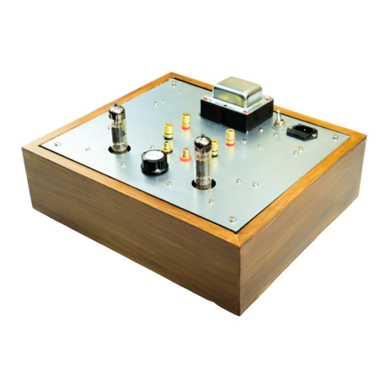
Caledonian Audio 6BM8-ECL82-SE-Classique Assembly Manual Mounting Components Install the following on the supplied mounting board: 1. IEC socket 2. Power transformer 3. Audio transformers (x2) 4. All PCBs 5. Speaker terminals 6. Audio input terminals 7. Potentiometer shows the location of the parts to be placed and secured on the Figure 12 mounting plate. Note that the placement diagram is a view from the top of the mounting board. - Page 20 Figure 13 - the complete system Screw/Nuts/Bolts Sizes All fixings are included in the kit. Table below summarizes the sizes of the fixings used for all parts. Part Fixings Output transformer • Slot Pan Head Machine Screw Brass Nickel Plated, M4, 20mm • RS PRO, M4, Bright Zinc Plated Steel Nylon Insert Lock Nut • Bright Zinc Plated Steel Plain Washer, 0.8mm Thickness, M4 Main transformer • Included in the transformer package Please make sure that the core of the transformer sits flushed on the mounting plate (i.e. no washer in between the mounting plate and the...
-
Page 21: Wiring 2
Caledonian Audio 6BM8-ECL82-SE-Classique Assembly Manual IEC Socket • Slot Countersunk Head Machine Screw Steel Bright Zinc Plated, M3, 12mm Power switch • Included in the power switch package Power earth lug and star ground point • Slot Pan Head Machine Screw Brass Nickel Plated, M4, 20mm • RS PRO Uninsulated Tin Plated Crimp Ring Terminal, M4 Stud Size, 0.5mm² 1.5mm², 22AWG to 16AWG •... -
Page 22: Wiring
Wiring Please make sure that you have all appropriate cables for this part. Refer to for the complete wiring diagram. You can also Figure 14 - wiring diagram cross-reference the wiring diagram with the schematics diagram shown in figure Figure 33 - Schematics Some notes: • Bear in mind that most of the connections / wires in the system are of high voltages (LETHAL) • It is advisable that you have all the high voltage cables insulated and use suitable wiring colour codes • Heater filament cables should be rated at 2 amps • Capacitors C1 (labeled C1L1 and C1R1) are located in between the RCA connectors and the potentiometer. They are the only capacitors/resistors, which are connected using point-to-point method. These capacitors can be seen in... - Page 23 Caledonian Audio 6BM8-ECL82-SE-Classique Assembly Manual Figure 14 - wiring diagram...
-
Page 24: Power Cables
Power Cables Start with connecting the ground earth connection from the IEC socket to the chassis ( Figure 15 - Ground earth from IEC socket wired to the chassis and secured by shakeproof washer and insert lock nut Figure 15 - Ground earth from IEC socket wired to the chassis and secured by shakeproof washer and insert lock nut... - Page 25 Caledonian Audio 6BM8-ECL82-SE-Classique Assembly Manual Connect the live (brown) and neutral (blue) from the IEC socket to the main power switch. ( Figure 16 - Live (brown) and neutral (blue) cables connecting the main power from the IEC socket to the power switch Figure 16 - Live (brown) and neutral (blue) cables connecting the main power from the IEC socket to the power switch...
- Page 26 Connect the main switch terminals (live and neutral) to the primary terminals of the main power transformer (0V and 240V). The two cables (brown and blue) will be carrying the mains input AC voltages (240VAC) from the switch to the transformer. See Figure 17 - Live (brown) and neutral (blue) cables from the power switch supplying main power to the power transformer Figure 17 - Live (brown) and neutral (blue) cables from the power switch supplying main power to the power transformer (0V, 240V)
-
Page 27: B+ Power Cables
Caledonian Audio 6BM8-ECL82-SE-Classique Assembly Manual B+ Power Cables Now we need to connect the B+ (a.k.a HT – basically the high DC voltage) from the power supply PCB onto both of the amplifier PCBs (and powering them up). In Figure 18 - Two cables (brown) connecting power transformer secondary terminals , you can see the twisted red cables (250V - 0) to the main power supply PCB (AC IN) coming out from the “B+ OUT” terminal on the PCB. Additionally, in Figure 20 - Twisted red cables carrying B+ voltage into the two we see the same twisted cables going to the B+ terminals on the amplifier boards amplifier PCBs. Connect the 0V OUT on the power supply PCB to the star ground – this is the yellow/green cable seen in Figure 18 - Two cables (brown) connecting power transformer secondary terminals (250V - 0) to the main power supply PCB (AC IN) - Page 28 Figure 19 - Completed main power supply board wiring Figure 20 - Twisted red cables carrying B+ voltage into the two amplifier boards...
-
Page 29: Heater Filament Power Cables
Caledonian Audio 6BM8-ECL82-SE-Classique Assembly Manual Heater Filament Power Cables Connect the 6.3V and 0V from the power transformer secondary (Sec2: 2A) to the filament power supply PCB as shown in Figure 21 - Two cables (red and black) connecting power transformer secondary terminals (6.3V, 0V) to the filament power supply PCB Figure 21 - Two cables (red and black) connecting power transformer secondary terminals (6.3V, 0V) to the filament power supply PCB (AC +/- IN) Now we will supply the heater filaments with the 6.3VDC from the heater filament power supply board to the H1 and H2 terminals on the amplifier boards. - Page 30 Figure 22 - Green cable connecting the 0V terminal on the filament power supply PCB and the star ground point. The black sleeve contains four wires carrying the 6.3VDC line (two positives and two negatives) from the filament power supply to the H1 and H2 terminals on both amplifier boards. The polarity on the H1 and H2 do not matter at all, as long as one receives a positive voltage and the other receives negative voltage. Figure 23 - Completed wiring for filament supply PCB...
-
Page 31: Audio Cables Wiring
Caledonian Audio 6BM8-ECL82-SE-Classique Assembly Manual Audio cables wiring We will now perform the wiring of the audio signals, starting from the point where the signal enters the system. Some of the wiring can be a bit tricky due to positions and lack of space, especially the potentiometer's pins however if you follow the steps and refer to the images provided, one should be able to perform these tasks with relative ease. - Page 32 Ground connections Now we will deal with the ground connections between the RCA terminals and the potentiometer. In this case, it is highly recommended that you use a single core copper cable that you can easily shape to fit the space in between potentiometer and RCA terminals. and Figure 25 - Single core insulated copper wire used for ground connections Figure show an example of how this is done (although they 26 - Potentiometer wiring really show the completed wiring – more than what this step is trying to do). The copper cables were shaped accordingly, and then soldered to the RCA ground terminals first and then to pin 1 on the potentiometer. Please note that there will be more cables being soldered to pin 1 of the potentiometer later but for now the single copper cable will be the only one.
-
Page 33: Potentiometer To Amplifier Pcb
Caledonian Audio 6BM8-ECL82-SE-Classique Assembly Manual Figure 26 - Potentiometer wiring Figure 27 - Potentiometer wiring - another angle Potentiometer to Amplifier PCB We will now connect the audio signal from the potentiometer to both of the amplifier PCBs, starting from the potentiometer end. - Page 34 On the potentiometer end, we would like to connect two cables (positive/hot and ground). The positive/hot cable is connected to Pin 2 (audio out) of the potentiometer and the ground goes to Pin 1 of the potentiometer (currently already being soldered with the single core copper cable). Again, refer specifically to Figure 25 - Single core insulated copper wire used for ground to see an example of how this is done.
-
Page 35: Amplifier Boards Wiring
Caledonian Audio 6BM8-ECL82-SE-Classique Assembly Manual Amplifier Boards Wiring First of all, lets have a look at the amplifier again on Figure 30 - Amplifier PCB revisit Table below describes all the terminals on this PCB. Item Label Function Connects To No. “H1”, “H2” Heater filament “0V” and “+V” on power in. These the filament power are the DC voltage supply PCB input for the valve... - Page 36 O/T- See example in . This is the white (twisted with Figure 29 - Amplifier Board Wiring red) cable connected to the “Anode” terminal on the output transformer O/T+ See example in . This is the red (twisted with Figure 29 - Amplifier Board Wiring white) cable connected to the “HT” terminal on the output transformer This terminal should already be connected by now, to the main power supply board. If not, please refer back to section: B+ Power Cables. Triode Ground Simply connect to the star ground. In the example below, a single core insulated copper core cable is used NFB See example in . This is the red cable connected...
-
Page 37: Speaker Output Wiring
Caledonian Audio 6BM8-ECL82-SE-Classique Assembly Manual Figure 30 - Amplifier PCB revisit Speaker Output Wiring The aim for this section is to connect the secondary winding of the output transformer to the speaker terminals. There are 4 speaker terminals in the system. Each channel contains the positive (hot) and negative (ground) cables. We will start with one channel first. Ground Connection Connect the “0” terminal on the Secondary winding of the output transformer to the ground (negative) speaker terminal. This is the single core insulated copper wire seen in . Then, Figure 31 - connecting the output transformer to speaker terminals connect the same speaker terminal to the star ground. - Page 38 Audio Signal Connection Connect the “8” terminal on the Secondary winding of the output transformer to the positive (hot) speaker terminal. This is the single core insulated copper wire seen in Figure 31 - connecting the output transformer to speaker terminals This is assuming that you will be using the 8 ohm speaker output terminal. Change this to another output impedance if necessary. Note that by now, there should be another cable connected to the speaker terminal. This is the NFB line, which we dealt with in section: NFB. Repeat the process for the other channel. The wiring for speaker output is now complete. Figure 31 - connecting the output transformer to speaker terminals...
-
Page 39: Assembly Completion
Caledonian Audio 6BM8-ECL82-SE-Classique Assembly Manual Assembly Completion We have now completed the assembly of the kit. What you have now should look something like seen in Figure 32 - Complete wiring Figure 32 - Complete wiring and components assembly... -
Page 40: Powering Up For The First Time
Powering Up For The First Time There are a number of items that you have to prepare/gather before/during powering up the amplifier. CAUTION– Valves can reach very high operating temperatures when in use and can cause burns if touched. Please see the checklist below: No. Item Note Done? IEC power cable For powering up the system Fuse A slow blow 2 amp fuse is needed. This is installed in the IEC socket Speakers Never power up the amplifier without speakers connected. Bad things happen when this is done. Use old (read cheap) pair of speakers when powering up for the first time... - Page 41 Caledonian Audio 6BM8-ECL82-SE-Classique Assembly Manual components. Pay particular attention to the B+ and heater voltages.
-
Page 42: Questions / Support
Questions / Support If you have any question, please get in touch with us at: support@caledonianaudio.co.uk... -
Page 43: Appendix
Caledonian Audio 6BM8-ECL82-SE-Classique Assembly Manual Appendix I. Amplifier PCB Components Label Specification Check packing list Check packing list Check packing list Check packing list Check packing list Check packing list Check packing list Check packing list Check packing list Check packing list Check packing list Check packing list Check packing list II. Main Power Supply PCB Components Label Specification Electrolytic Capacitor, 47 µF, 350 V, Radial Leaded, 16 mm C2, C3 Electrolytic Capacitor, Snap-in, 100 µF, 400 V Film Capacitor, 0.1 µF, 400 V, PET (Polyester) D1, D2, Silicon Carbide Schottky Diode, Z-Rec 600V Series, Single, 600 V, 2 A, D3, D4 3.3 nC, TO-220 Through Hole Resistor, 100 kohm, 350 V, Metal Film, Axial Leaded, 500 mW R1, R2, Axial Wirewound Resistor 220Ω ±5% 7W R3, R4 III. Heater Filament PCB Label Specification C5, C6 Nichicon Aluminium Electrolytic Capacitor 15000μF 10V dc 16mm... -
Page 44: Iv. Schematics 4
IV. Schematics Figure 33 - Schematics...
Need help?
Do you have a question about the 6BM8/ECL82 SE and is the answer not in the manual?
Questions and answers