Table of Contents
Advertisement
Quick Links
Advertisement
Table of Contents

Summary of Contents for Mini?Cam Proteus CRP150
- Page 1 Mini‐Cam Proteus Original Instruction Manual Page | 1 ...
- Page 2 This document is applicable to the Proteus™ system. A standard system and available options are covered by this document. Depending on your system configuration you may lack some of the features mentioned in this document. Disclaimer Hardware and software mentioned in this document are subject to continuous development and improvement. Consequently, there may be minor difference between the information in the document and the performance or design of the product. Specifications, dimensions and other statements in this document are subject to change without prior notice. Mini‐Cam Ltd and its suppliers shall not be liable for any damages related to this software or hardware, or for any other damages whatsoever caused by the use of or inability to use any Mini‐Cam product. This is applicable even if Mini‐Cam has been advised of the damage risk. Under any circumstances, Mini‐Cam’s entire liability shall be limited to replace such defective software or hardware that was originally purchased from Mini‐Cam. Mini‐Cam Ltd, Unit 4 Yew Tree Way, Golborne, Warrington, Cheshire, WA3 3JD. Phone: +44 1942 270 524 – Fax: +44 1942 273 735 Page | 2 ...
-
Page 3: Table Of Contents
Table of Contents Text Conventions ............................ 6 Danger, Caution and Note ........................ 6 Bold Font ............................. 7 Lists .............................. 7 Menu Selections .......................... 7 Product description .......................... 8 EC Declaration of Conformity ......................... 9 System Overview .......................... 1 0 Warnings, safety measures & care ....................... 1 1 Before first use .......................... 1 3 Safety measures .......................... 1 5 Maintenance ............................. ... - Page 4 Crawler wheels .......................... 3 3 Maintenance .......................... 3 3 Technical details .......................... 3 3 Camera module CAM028 ........................ 3 4 Connections and descriptions ...................... 3 5 Information and care ........................ 3 6 Pressurisation .......................... 3 6 Cleaning ............................ 3 6 Maintenance .......................... 3 6 Technical details .......................... 3 6 Camera module CAM027 ...
- Page 5 Power ON sequence ........................ 4 8 Power OFF sequence ........................ 4 9 Crawler function keys ........................ 4 9 Survey function keys ........................ 5 0 Media function keys ........................ 5 0 Camera function keys ........................ 5 1 Snapshot key .......................... 5 1 Recording and playback keys ...................... 5 1 QWERTY keys .......................... 5 1 Connections and descriptions ...................... 5 2 Front view ............................. 5 2 Rear view ............................ 5 3 Information and care ........................ ...
-
Page 6: Text Conventions
Text Conventions Danger, Caution and Note In this user manual the following symbols are used: Danger DANGER! Danger means a potentially dangerous situation that can cause death or severe bodily injury. The icon identifies the type of risk. Caution CAUTION! Caution means that the system or equipment can be damaged or data lost. The icon identifies the type of risk. Note NOTE! Notes are used to convey throughout this manual important information or guidance for system use. Page | 6 ... -
Page 7: Bold Font
Bold Font Bold font is used for important words (For example: This must not be done in reverse order). Lists Lists are marked as follows: • Item 1 • Item 2 Procedures that must be performed in a specific order appear in numbered lists like this: 1. Perform this step first. 2. Perform this step second. Menu Selections When describing control unit operation, sequential menu selections are described in the following format: Setup > Camera >Enable Backeye Camera > OK This example describes pressing the Setup key and selecting the Camera and Backeye options, and finally pressing the OK key. Page | 7 ... -
Page 8: Product Description
Product description The inspection system PROTEUS™ is a modular system designed for, but not limited to, inspecting pipeline systems. Using a variety of colour cameras, optional modules and accessories, the PROTEUS™ platform offers everything needed for professional pipeline inspection. The comprehensive list of modules and accessories allow inspection of pipes equal to and greater than 150mm diameter. Different wheel sets allow the crawler to be centred in pipe sizes from 150mm to 600mm. The Auxiliary Light with Backeye camera provides additional forward illumination and a colour rear view camera with illumination to aid manoeuvring the crawler in reverse. The system uses a control unit with twin joysticks, QWERTY keyboard, and reporting software developed in‐house by Mini‐Cam. Built using high quality materials and state of the art technology the PROTEUS™ system is a robust and powerful tool for use in harsh environments. Page | 8 ... -
Page 9: Ec Declaration Of Conformity
EC Declaration of Conformity CE Declaration We Mini‐Cam Ltd. Unit 4 Yew Tree Way, Stonecross Park, Golborne, Warrington, WA3 3JD hereby declare that the product PROTEUS™ to which this declaration refers is in compliance with the following standards or standardizing documents: EN61000‐6‐2:2005 Generic standards – Immunity for industrial environments EN61000‐6‐4:2007 Generic standards – Emission for industrial environments EN61010‐1:2010 Safety requirements for electrical equipment for measurement, control, and laboratory use. EHSR MSD Essential Health and Safety Requirements of Machinery Safety Directive The following are the stipulated operating and environmental conditions for said compliance: Residential, business, commercial, small‐company and light industrial environments. This declaration is based on test report(s) of the relevant EMC testing laboratory. Page | 9 ... -
Page 10: System Overview
System Overview The inspection system PROTEUS™ consists of the following main components: • Control Unit (1) • Cable Reel (2) • Crawler (3) • Camera (4) A typical configuration is shown in this illustration: 1 2 NOT TO SCALE 3 Page | 10 ... -
Page 11: Warnings, Safety Measures & Care
Warnings, safety measures & care Please read the safety measures closely and observe them. They preserve your own safety, the safety of co‐workers as well as the prevention of damage to the PROTEUS™ inspection system and its components. CAUTION! The operator of the PROTEUS™ inspection system must be trained by either Mini‐Cam or one of its authorised representatives before using the system. CAUTION! Despite all of the safety functions built into the system, the operator is not exonerated in any way from his/her duty of care. Thus the user alone is responsible for any damage caused as a result of misuse. CAUTION! If the equipment is used in a manner not specified by the manufacturer, the protection provided by the equipment may be impaired. DANGER! Risk of deadly injuries from electrical current! The mains plug and or IEC connector of the PSU is the supply isolation device and must be easily accessible. Page | 11 ... - Page 12 DANGER! Risk of deadly injuries from electrical current! • The power supply for the crawler is nominally 120 volts DC which can be considered hazardous, however this supply cannot be switched on unless the control unit is connected to the cable reel and the cable is connected to the crawler. Consequently this supply is not accessable and as soon as any connection is exposed the power supply will be automatically shut off. • This hazardous voltage may be exposed if the control unit, cable reel or crawler is opened while the system is operational. Therefore the modules of the system should only be opened by a Mini‐Cam Service Centre. • There are no user serviceable components within any module in the system. DANGER! Risk of deadly injuries from electrical current! Only use an appropriately rated and approved cordset in accordance with the regulation of the country in which this system is used. DANGER! Risk of deadly injuries from electrical current! Although the cable reel and crawler could be used in wet environments the external PSU is for indoor use only (as marked on its label) and must not be used in wet areas. DANGER! Risk of deadly injuries from electrical current! ...
-
Page 13: Before First Use
Before first use Please notice the following sources of risk for serious or deadly injuries: CAUTION! Risk of deadly injuries from electrical current! • Ensure that no fluids can enter the control panel or penetrate the housing of the cable reel. In case this happens, immediately disconnect the power supply and inform the appropriately trained staff or Mini‐ Cam Service Centre. • Ensure that the electrical connection cables are intact and that they cannot be bent or crushed. If you find cable damage, immediately disconnect the power supply and inform the appropriately trained staff or Mini‐Cam Service Centre. • Work on the electronics, which are not covered in this document, shall only be carried out by trained specialist staff or a Mini‐Cam Service Centre. • Maintenance and repair work, which is not covered in this document, shall only be carried out by trained specialist staff at a Mini‐Cam Service Centre. CAUTION! Risk of serious injuries by falling crawler! When preparing the system for operation pay attention to the crawler position, that it is not too close to the manhole. When testing the driving function, the crawler might fall into the manhole. Any person in the manhole may suffer serious injuries. CAUTION! Hazard of infection and contamination of fresh water! ... - Page 14 CAUTION! Explosion hazard! Do not use the inspection system in pipelines which might have contained explosive substances, such as gas or solvents. If this kind of application should be required, contact Mini‐Cam Ltd to obtain information on system components destined for this purpose. CAUTION! Suffocation hazard! Before and while lowering the crawler into the pipe system it is necessary to perform a safety test with a certified gas detector. Page | 14 ...
-
Page 15: Safety Measures
Safety measures The staff assigned to tasks involving the PROTEUS™ inspection system must have read and understood this user manual completely before the start of the work. This applies equally to the staff who only work on the inspection system infrequently, e.g. for maintenance, repair or retrofitting work. NOTE! The operator of this inspection system is obliged to ensure a safe and hazard‐free operation. This may be achieved by the following measures: • Making the user manual available on the site of the use of the inspection system at all times. • Check lists for maintenance and care. • Regular reviews of the safety and hazard conditions NOTE! Safety of persons! The staff for operation, maintenance and upgrading must have specialist expertise or be instructed by competent individuals. Competent individuals must have adequate knowledge of the PROTEUS™ inspection system based on technical training and experience. They must be familiar with the relevant work safety regulations and accident prevention rules to an extent that they are capable of judging the inspection system’s operational safety. They must: • Observe the operating manual for the workplace. • Observe the relevant work safety regulations and accident prevention rules. • Seek instruction for the handling of hazardous substances. •... -
Page 16: Maintenance
described in this user manual. • Keep the system clean. Observe the individual cleaning instructions for this purpose. Maintenance To ensure the maximum service life of the PROTEUS™ system the individual modules and accessories belonging to the system have to be independently maintained and kept clean. Moving parts, in particular, can have improved operational life by frequent professional cleaning after inspections. Also, the risk to the operator of infection can be significantly reduced by using a cleaned system. Take notice of the following comments on general maintenance: • Keep the entire system clean and clean the system directly after each inspection. • Thoroughly wash down the parts of the system that have come into contact with moisture and then dry them with a clean and dry cloth. • Keep all electrical connections and contacts free of dirt, grease and moisture at all times. • Never bend the cable of the system and avoid knots. • Clean the cable with a rag when retracting. • Regularly grease all exposed O‐rings using O‐ring lubricant as required in the maintenance instruction. • Use only suitable display cleaners for cleaning the display as required in the maintenance instruction. • Use only clean and dust free cloths for cleaning the display. • Use water for cleaning without the addition of cleaning agents or solvents. For detailed maintenance instructions for individual modules and accessories please read the comments in the description for each module. The specific maintenance work steps will also be explained. NOTE! The operator of the system is responsible for the proper disposal! See ... -
Page 17: Cleaning
Cleaning To minimise down time and subsequent repairs it is necessary to keep your PROTEUS™ system clean. Please follow the instructions below to help avoid disruption. CAUTION! Risk of fatal injuries caused by electrical current! Ensure that no fluids can enter the control panel or penetrate the housing of the cable reel. In case this happens, immediately disconnect the power supply and inform the Mini‐Cam Service Centre. CAUTION! Risk of fatal injuries caused by electrical current! For all cleaning and maintenance work disconnect the system from the power supply. General cleaning work CAUTION! High‐pressure cleaners must not be used. It can cause considerable damage to the crawler, camera and other system components. Cleaning agents or solvents must not be used. These can damage the seals and other materials on the system. Only clean water should be used. • Clean the crawler and camera with water after the first inspection. Only after this should you loosen electrical connections. • Immediately fit the protective caps after removing electrical connections. •... -
Page 18: Removal And Fitting Of The Cable Reel Dirt Tray
Removal and fitting of the cable reel dirt tray After use, dirt and water will have collected in the cable reel. A tray is built into the bottom of the cable reel to collect this, which can be removed for cleaning. 1. Pull out the tray. 2. Remove dirt, water and debris. 3. Push the tray back into position. Page | 18 ... -
Page 19: Checking Plug And Socket Connections
Checking plug and socket connections To ensure reliable operation it is important that the electrical connections are not damaged and kept clean and dry. It is important to check before and after each use of the inspection system. • Check the contacts on the camera back plate. • Check the contacts on the crawler camera connector (with care). • Check the contacts on the crawler cable connector. • Check the contacts on the cable reel connector. • Check the contacts on the control unit. • Check the contacts on the auxiliary module. Clean the pins and connectors from dirt and moisture using an electronic contact cleaner aerosol. NOTE! • Disconnect the power supply from the system. • Check the O‐rings for damage and replace if necessary. • Grease the O‐rings if necessary using O‐ring lubricant. Page | 19 ... -
Page 20: Connecting The Proteus™ System
Connecting the PROTEUS™ system Fitting and removal of crawler wheels 2 1 3 1. Ensure the quick release wheel retainer is aligned with the axle (1). 2. Slide wheel (2) on to the crawler axle (3). 1. Turn the wheel retainer bolt clockwise to lock the wheel onto the axle. NOTE! To remove the wheel turn the retainers bolt anticlockwise, ensure that the retainer is aligned with the wheel axle, and slide the wheel off the crawler axle. Page | 20 ... -
Page 21: Connection Cabling Between Control Unit And Cable Reel
Connection cabling between control unit and cable reel Connect the link cable to the back of the control unit and to the side of the cable reel, as illustrated: 3 1 2 1. Plug the male plug of the link cable into the back of the control unit (1). Notice the orientation of the plugs. 2. Plug the female plug of the link cable into the side of the cable reel (2). Notice the orientation of the plugs. 3. Turn the retaining ring clockwise, as viewed from the cable, to lock the plugs into their sockets (3). NOTE! To remove the connectors turn the retaining ring anticlockwise. Page | 21 ... -
Page 22: Connection Cabling Between Cable Reel And Crawler
Connection cabling between cable reel and crawler Connect the cable reel cable to the back of the crawler as illustrated: 2 4 3 1 1. Plug the female plug of the cable reel cable (1) into the back of the crawler (2). Notice the orientation of the plug (3). 2. Turn the retaining ring (4) clockwise, as viewed from the cable, to lock the plug into the socket (2). The retaining ring is not able to unscrew itself during use. Page | 22 ... - Page 23 1. To unscrew the retaining ring you must pull the ring away from the crawler body before rotating anticlockwise. NOTE! Always fit the protective caps when the crawler, camera or auxiliary module are not in use to protect from ingress of dirt and moisture. Page | 23 ...
-
Page 24: Connection Of Camera To Crawler
Connection of camera to crawler Connect the camera to the crawler as illustrated: 4 3 2 1 1. Ensure the connections are free of debris, dirt and moisture. 2. Ensure the locking ring (1) is rotated fully clockwise, as viewed in the diagram. 3. Notice the orientation of the camera (2). Orientation pin locates here (3). Fit the camera. 4. Turn the retaining ring (1) anticlockwise, as viewed in the diagram, to lock the camera onto the crawler. 5. Turn the grub screw (4) to lock the retaining ring in position using 3mm Allen key. 6. Removal is the opposite of fitting. NOTE! Always fit the protective caps when the crawler, camera or auxiliary module are not in use to protect from ingress of dirt and moisture. ... -
Page 25: Connection Of Auxiliary Module To Crawler
Connection of auxiliary module to crawler Connect the auxiliary module, ALB300, to the crawler as illustrated: 2 1. Remove the protective cap screws (1) 2. Remove protective cap (2) 3. Fit auxiliary module to crawler. Notice the orientation as shown in the diagram 4. Fasten screws, M4x45mm, to fix the auxiliary module onto the crawler (3) NOTE! Always fit the protective caps when the crawler, camera or auxiliary module are not in use to protect from ingress of dirt and moisture. Page | 25 ... -
Page 26: Pressurising The Proteus™ System
Pressurising the PROTEUS™ system Before use it may be necessary to pressurise the crawler, camera and auxiliary module. The pressure within each of the modules must be checked before the inspection begins. NOTE! The internal pressure of each pressurised module may vary. Refer to the specific module technical specification for correct pressure information. The control unit displays the internal pressure reading for each of the pressurised modules when the system power is ON. CAUTION! Use a pressure reducing valve when pressuring a module. Never attempt to connect the gas bottle directly to a system module. Check list for adjusting internal pressure of modules 1. Connect the crawler to the control unit and apply power. 2. Unscrew the pressure valve protective cap. 3. Screw on the valve connection adaptor. 4. Fill the module with CO2 or Nitrogen while monitoring the pressure on the control unit. 5. When the pressure reading indicates that internal pressure is correct stop filling the module. 6. Remove the valve connection adaptor. 7. Refit the protection cap. Page | 26 ... -
Page 27: Pressurising The Crawler
Pressurising the crawler To pressurise the crawler locate the valve position and follow the check list on page 26: Pressure valve Page | 27 ... -
Page 28: Pressurising The Camera
Pressurising the camera To pressurise the camera locate the pressure valve and follow the check list page 26: Pressure valve Page | 28 ... -
Page 29: Testing The System
Testing the system Test the system before use to make sure the system performs correctly. CAUTION! Risk of serious injuries by falling crawler! During the testing of the system make sure that the crawler is not positioned too close to the open manhole! When testing the driving functions the crawler may fall into the manhole. Any person in the manhole may suffer serious injuries. CAUTION! Risk of disorientation and temporary blindness! The illumination on the PROTEUS™ system uses high power LED lighting with narrow angle secondary optics. During the testing and use of the system never look directly at the camera or auxiliary module illumination. When checking the illumination use a low power setting and view from an angle greater than 50 degrees from the centre of the module. Check the following system functions: 1. Control function of the crawler using the left joystick: a. Drive forwards and backwards. b. Steer left and right. 2. Control function of the camera using the right joystick (If Pan and Rotate camera head): a. Rotation left and right. b. Pan up and down. 3. Lighting control of camera head and auxiliary module (if fitted): a. Turn the light intensity up and down. 4. -
Page 30: Lowering The Crawler Into The Manhole
Lowering the crawler into the manhole Use the built in lowering device and lower the crawler into the manhole. CAUTION! Risk of damage to the crawler and camera! 4 Lower the crawler slowly into the manhole. Avoid contact with the manhole. Settle the crawler on the bottom of the manhole gently. 3 1. Lower the crawler into the manhole using the rope (1) with hook (2) on the lowering device (3). 2. Balance the crawler by means of the crawler cable (4) so that it does not contact the manhole. 3. Detach the hook (2) from the crawler lowering device (3). NOTE! To retrieve the crawler from the manhole use the rope (1) and hook (2) to attach to the crawler lowering device (3). Lift the crawler out of the manhole, balancing the crawler by using the crawler cable (4). Page | 30 ... -
Page 31: Crawler Crp150
Crawler CRP150 The crawler CRP150 can operate in pipes from 150mm to 600mm diameter. The crawler has the following features: • Multi‐Frequency Sonde location transmitter • A selection of crawler wheels for all surface conditions • Constant monitoring of the pitch and roll • Constant monitoring of the internal pressure • Optional auxiliary light module with Backeye camera The crawler is pressure‐tight up to 1bar and thus suitable for inspections up to 10m water depth. All six wheels of the crawler are driven by two motors ensuring that it is possible to move and steer the crawler on extremely difficult surfaces. Page | 31 ... -
Page 32: Connections And Descriptions
Connections and descriptions 7 9 8 2 1 3 1. Connector for cable reel connection 2. Lowering device 3. Crawler axles 4. Crawler wheels 5. Pressure valve 6. Connector for the auxiliary module 7. -
Page 33: Information And Care
Information and care Pressurisation The crawler must always be correctly filled with CO2 or Nitrogen. The control unit displays the internal pressure. Cleaning Ensure the crawler is thoroughly cleaned after each inspection. Ensure the connectors are free from dirt and moisture. Always fit the dust caps immediately after disconnecting the crawler from the system. Crawler wheels For inspection in various pipe systems always use the appropriate wheel combinations. Maintenance Ensure the all screw threads and connections are free from dirt. CAUTION! High‐pressure cleaners must not be used. It can cause considerable damage to the crawler, camera and other system components. Cleaning agents or solvents must not be used. These can damage the seals and other materials on the system. Only clean water should be used. CAUTION! Risk of fatal injuries caused by electrical current! For all cleaning and maintenance work disconnect the system from the power supply. Technical details Product ID: CRP150 Dimensions (L*W*D): 320*120*100mm Power Consumption: 100W Weight: 9.25 Kg Temperature Range: ‐10 ~ +50 degrees C ... -
Page 34: Camera Module Cam028
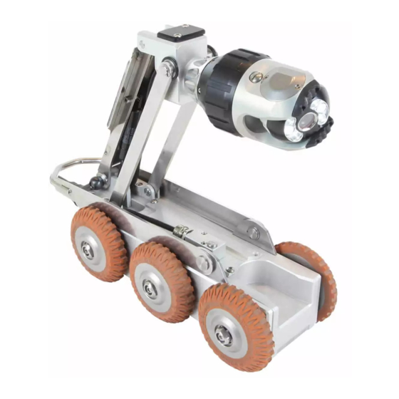
Camera module CAM028 The camera module CAM028 provides a high resolution, colour, pan and rotate camera for the PROTEUS™ platform. It has the following features: • High resolution colour CCD image sensor • Powerful LED lighting with narrow beam width lenses • Endless rotation range • Panning range of +/‐ 135 degrees • Motorised focus control • Internal pressure monitoring • Impact resistant with user replaceable rubber protectors The camera module is pressure‐tight up to 1bar and thus suitable for inspections up to 10m water depth. Page | 34 ... -
Page 35: Connections And Descriptions
Connections and descriptions 1 6 5 1. Camera connector 2. Pressure valve 3. LED illumination 4. Rubber protector 5. Camera protection skid 6. Camera protection skid screws (x6) 7. Camera lens 8. Serial number location Page | 35 ... -
Page 36: Information And Care
Information and care Pressurisation The camera module must always be correctly filled with CO2 or Nitrogen. The control unit displays the internal pressure. Cleaning Ensure the camera module is thoroughly cleaned after each inspection. Ensure the connector is free from dirt and moisture. Always fit the protective cap immediately after disconnecting the camera module from the system. Maintenance Ensure that all screw threads and connections are free from dirt. Replace the rubber protectors when worn or damaged. CAUTION! High‐pressure cleaners must not be used. It can cause considerable damage to the crawler, camera and other system components. Cleaning agents or solvents must not be used. These can damage the seals and other materials on the system. Only clean water should be used. Technical details Product ID: CAM028 Dimensions (L*W*D): 120*73*73mm Power Consumption: 10W Weight: 0.85Kg Temperature Range: ‐20 ~ +50 degrees C Environmental Protection: Pressurised Internal Pressure: 0 ~ 800mBar ... -
Page 37: Camera Module Cam027
Camera module CAM027 The camera module CAM027 provides a high resolution, colour, axial camera for the PROTEUS™ system. It has the following features: • High resolution colour CCD image sensor • Powerful LED lighting with narrow beam width lenses • Motorised focus control The camera module is not pressurised but is suitable for inspections up to 10m water depth. Page | 37 ... -
Page 38: Connections And Descriptions
Connections and descriptions 1 1. Camera connector 2. LED illumination 3. Camera lens 4. Serial number location Page | 38 ... -
Page 39: Information And Care
Information and care Pressurisation The camera module is not pressurised. Cleaning Ensure the camera module is thoroughly cleaned after each inspection. Ensure the connectors are free from dirt and moisture. Always fit the protective cap immediately after disconnecting the camera module from the system. Maintenance Ensure that the camera connector is free from dirt. CAUTION! High‐pressure cleaners must not be used. It can cause considerable damage to the crawler, camera and other system components. Cleaning agents or solvents must not be used. These can damage the seals and other materials on the system. Only clean water should be used. Technical details Product ID: CAM027 Dimensions (L*W*D): 63*52*52mm Power Consumption: 7W Weight: 0.25Kg Temperature Range: ‐20 ~ +50 degrees C Environmental Protection: IP67 Page | 39 ... -
Page 40: Auxiliary Module Alb300
Auxiliary module ALB300 The auxiliary module ALB300 provides additional illumination for the forward view camera and a rear view, high resolution, colour, camera for the PROTEUS™ platform. It has the following features: • High resolution colour CCD image sensor • Powerful LED lighting with narrow beam width lenses The auxiliary module is not pressurised but is suitable for inspections up to 10m water depth. Page | 40 ... -
Page 41: Connections And Descriptions
Connections and descriptions 2 1. Forward LED illumination 2. Rear view camera 3. Connector 4. Serial number location Page | 41 ... -
Page 42: Information And Care
Information and care Pressurisation The auxiliary module is not pressurised. Cleaning Ensure that the auxiliary module is thoroughly cleaned after each inspection. Ensure the connector is free from dirt and moisture. Always fit the protective cap immediately after disconnecting the auxiliary module from the system. Maintenance Ensure that all screw threads and electrical connections are free from dirt and moisture. CAUTION! High‐pressure cleaners must not be used. It can cause considerable damage to the crawler, camera and other system components. Cleaning agents or solvents must not be used. These can damage the seals and other materials on the system. Only clean water should be used. Technical details Product ID: ALB300 Dimensions (L*W*D): 84*68*50mm Power Consumption: 4W Weight: 0.32Kg Temperature Range: ‐20 ~ +50 degrees C Environmental Protection: IP67 ... -
Page 43: Cable Reel Rmp150
Cable reel RMP150 The cable reel RMP150 is a portable cable reel for the PROTEUS™ system equipped with up to 200m of cable. It has the following features: • Up to 200m of cable • Cable layering mechanism • Meterage wheel • Manual winding arm • Friction brake The cable reel is suitable for installation in a vehicle and also for use stand alone for portable applications. Page | 43 ... -
Page 44: Connections And Descriptions
Connections and descriptions 5 6 2 4 7 1. Dirt tray. 2. Winding arm and handle. 3. Cable layering mechanism. 4. Meterage wheel. 5. Friction brake. 6. Connection to control unit. 7. Connection to crawler. Page | 44 ... -
Page 45: Information And Care
Information and care CAUTION! Risk of injury to persons! Due to the weight of the cable reel, RMP150, it must be lifted by two people. Cleaning Ensure that the cable is thoroughly cleaned after each inspection. Use a wet rag when winding the cable back onto the drum. Ensure the connector for the crawler is free from dirt and moisture. Always fit the dust caps immediately after disconnecting the cable reel from the system. Empty the dirt tray when required. Maintenance Ensure that all screw threads and connections are free from dirt. CAUTION! High‐pressure cleaners must not be used. It can cause considerable damage to the crawler, camera and other system components. Cleaning agents or solvents must not be used. These can damage the seals and other materials on the system. Only clean water should be used. Technical details Product ID: RMP150 Dimensions (L*W*D): 530*280*520mm Power Consumption: 1W Weight: 24Kg (150m) or 28Kg (200m) Temperature Range: ‐20 ~ +50 degrees C Environmental Protection: IP54 ... -
Page 46: Control Unit Ccu208
Control unit CCU208 The control unit CCU208 is a robust and portable control unit for the PROTEUS™ system. It controls the functions and reports the status of the attached modules. It has the following features: • Scalable internal solid state storage (32GB minimum) • Data transfer via USB and SD card • Daylight readable display (1024x768 pixels) • Video recording in MPEG‐4 AVC/H.264 formats • Pictures saved in JPG format • Customisable colour on screen text overlay • Video output of live video with onscreen text (Optional) • Audio output • Ergonomic design • IP54 rated The control unit CCU208 enables the operator to record video and photographic surveys, generate survey reports, and export the data via USB or SD card. The control unit can generate on screen text that is overlaid onto the recorded video in various colours and positions, allowing easy customisation. Page | 46 ... -
Page 47: Ccu208 Overview
CCU208 overview 5 6 2 7 8 1. Daylight viewable screen, 1024x768 pixels. 8. Survey Function keys. 2. Left joystick for crawler control. 9. Media function keys. 3. Right joystick for camera control. 10. Camera function keys. 4. Speaker. 11. Snapshot key. 5. ON/OFF button. 12. Recording and playback keys. 6. ALL STOP button. 13. QWERTY keys. 7. Crawler function keys. Page | 47 ... -
Page 48: On/Off Button
ON/OFF button Used to turn the control unit ON and OFF. This button does not enable power to the crawler. By design, the control unit will power on but power is not automatically applied to the crawler. A green light next to this button indicates that the CCU is powered on. ALL STOP button Used to enable / disable power to the crawler. When power to the crawler is disabled a red light next to this button is illuminated. • When the control unit is powered ON this key must be pressed to enable power to the crawler. • When the crawler is powered ON, pressing this key will disable power to the crawler. • The ALL STOP button can be used in case of emergency to stop the crawler and disable the power. NOTE! The ALL STOP button must be pressed to disable the power to the crawler before disconnecting any part of the system. Power ON sequence 1. With the system power OFF, connect all system components: Cable reel, crawler, camera 2. Press ON/OFF button to power the control unit ON. 3. Read and acknowledge the onscreen prompt. 4. Press the ALL STOP button. 5. If the control unit detects a crawler connected, the system will fully power up. The red light next to the ALL STOP button will turn off. Video will be displayed and crawler/camera status information will be displayed on the right hand side of the screen. a. If the control unit does not detect a crawler connected, the system will not fully power up. The control unit will sound a beep several times and the red light next to the ALL STOP button will be illuminated. If this should happen first check all connections on the system are made correctly. If the problem persists then contact the Mini‐Cam Service Centre or accredited Mini‐Cam partner in your country. ... -
Page 49: Power Off Sequence
Power OFF sequence 1. Press the ALL STOP button. The red light next to this button will illuminate. 2. Press the ON/OFF button and press OK to confirm. 3. The control unit will now power down. 4. The system can now be disconnected. NOTE! Always fit the protective caps when the crawler, camera or auxiliary module is not in use to protect from ingress of dirt and moisture. Crawler function keys 1 2 3 1. Cruise control – Forward: a. Each press increases speed until maximum speed is reached. b. When the crawler is reversing, each press slows the crawler speed. 2. Stop: a. Crawler stops moving. Power is still enabled. 3. Cruise control – Reverse: a. Each press increases speed in reverse until maximum speed is reached. b. When the crawler is traveling forward each press slows the crawler speed. 4. Crawler settings: a. -
Page 50: Survey Function Keys
Survey function keys 1 2 3 1. Meterage. a. Change meterage manually. b. Change position of meterage on the screen. 2. Text. a. Change text colour 3. Survey Folder. a. Start ProPipe or WinCan survey. Media function keys 1 2 3 1. Copy. a. Copy files from one media source to another. 2. Storage media. a. Choose storage media – Internal/USB/SD card. 3. Gallery. a. -
Page 51: Camera Function Keys
Camera function keys 1 3 1. Digital zoom 2. Camera illumination 3. Focus – 4. Focus + 5. Camera home a. Automatically move camera to home position. Camera CAM028 only. 6. Camera settings Snapshot key Press this key to take a JPG image of the live video or video during playback. Recording and playback keys These keys control the recording and playback of video files. QWERTY keys These keys allow the user to enter text for onscreen text or survey comments. Page | 51 ... -
Page 52: Connections And Descriptions
Connections and descriptions Front view 1 3 2 1. External media – USB and SD card slots. a. External media status LED’s. i. Blue – Media is plugged in but is not in use. ii. Orange blinking – Media is currently selected and in use. iii. Green – Media is safe to remove from the control unit. 2. External media eject button. a. Press this button for 1 second and release. This will instruct the control unit that you wish to unmount the external storage media. When the LED status indicators are green it is safe to remove the media. 3. External media protection cover. a. To protect the connectors from dirt and moisture. NOTE! Always fit the external media protection cover into position to protect from ingress of dirt and moisture. Page | 52 ... -
Page 53: Rear View
Rear view 1 3 1. External power input (24VDC). a. This provides power for the crawler and charges the control unit internal battery. 2. Connection to cable reel. 3. Expansion slot protection cover. a. To protect the expansion slot from ingress of dirt and moisture. NOTE! Always fit the expansion slot protection cover into position to protect from ingress of dirt and moisture. Page | 53 ... -
Page 54: Information And Care
Information and care Cleaning Ensure that the control unit is thoroughly cleaned after each inspection. Use a damp rag when cleaning. Ensure the connectors are free from dirt and moisture. Always fit the dust caps immediately after disconnecting the control unit from the rest of the system. Maintenance Ensure that all screw threads and connections are free from dirt. CAUTION! High‐pressure cleaners must not be used. It can cause considerable damage to the control unit, crawler, camera and other system components. Cleaning agents or solvents must not be used. These can damage the seals and other materials on the system. Only clean water should be used. CAUTION! The control unit is rated to IP54 providing that the external media and expansion slot covers are fitted in place. CAUTION! It must be noted that although the cable reel and crawler are for use in wet environments the control unit is for indoor use but may also be used outdoor in very light rain. The external PSU is for indoor use only as marked on its label. Technical details Product ID: CCU208 Dimensions (L*W*D): 430*280*150mm Power Consumption: 120W Weight: 5.5Kg Temperature Range: ‐10 ~ +40 degrees C ... -
Page 55: External Power Supply Unit Psp24
External Power Supply Unit PSP24 The external PSU PSP24 provides power to the PROTEUS™ inspection system. It is required to charge the internal battery of the control unit and also to power the crawler. PSU Specifications Mini‐Cam Part Number: PSP24 Safety Model No: GS160A24 DC Voltage: 24V Rated Current: 6.67A OUTPUT Current Range: 0 ~ 6.67A Rated Power: 160W Voltage Tolerance: +/‐ 3% Load Regulation: +/‐ 3% Voltage Range: 85 ~ 264VAC Frequency Range: 47 ~ 63Hz INPUT Efficiency: 92.5% AC Current: 1.85A 115VAC 1A 230VAC ... - Page 56 WEEE E Stateme ent Under th he European n Union (“EU ”) Directive on Waste El lectrical and Electronic E quipment, D Directive 2002/96 6/EC, produc cts of “electr ical and elec ctronic equip pment” canno ot be discard ded as munic cipal waste an nymore and manufactur ers of covere ed electronic c equipment t are obligate ed to take ba ack such product s at the end of their usef ful life. Mini‐ ‐Cam will com mply with th e product ta ake back requirem ments at the end of life o...
Need help?
Do you have a question about the Proteus CRP150 and is the answer not in the manual?
Questions and answers