
Summary of Contents for Hobut MultiPower M850-LTHN-1
- Page 1 M850-LTHN MultiPower Installation and Operation Manual (Revision 1.0.0) July 2014 M 8 5 0 - L T H N M u l t i P o w e r I n s t a l l a t i o n a n d O p e r a t i o n M a n u a l Page 1...
-
Page 2: Table Of Contents
Table of Contents Chapter 1: Meter Overview and Specifications Hardware Overview 1.1.1 Voltage and Current Inputs 1.1.2 Model Number plus Option Codes 1.1.3 Measured Values Specifications Compliance Chapter 2: Mechanical Installation Introduction / Cut-Out Details Panel Mounting Procedure Terminal Block Notes Chapter 3: Electrical Installation Considerations When Installing Meters Voltage and Power Supply Connections... - Page 3 Chapter 6: Configuring the M850-LTHN Using the Front Panel System Type Programming Configure CT Ratio Settings 6.2.1 CT Ratio Programming Configure VT Ratio Settings 6.3.1 VT Ratio Programming Configure Max Demand Time Setting 6.4.1 Max Demand Time Setting Appendix A: Modbus Registers 3X and 4X Registers Register Addresses and Modes Appendix B: M850-LTHN Quick Start Guide...
-
Page 4: Chapter 1: Meter Overview And Specifications
Free software for monitoring and logging available on request or visit http://www.hobut.co.uk/images/HOBUT-MViewV02.zip M 8 5 0 - L T H N M u l t i P o w e r I n s t a l l a t i o n a n d O p e r a t i o n M a n u a l... -
Page 5: Voltage And Current Inputs
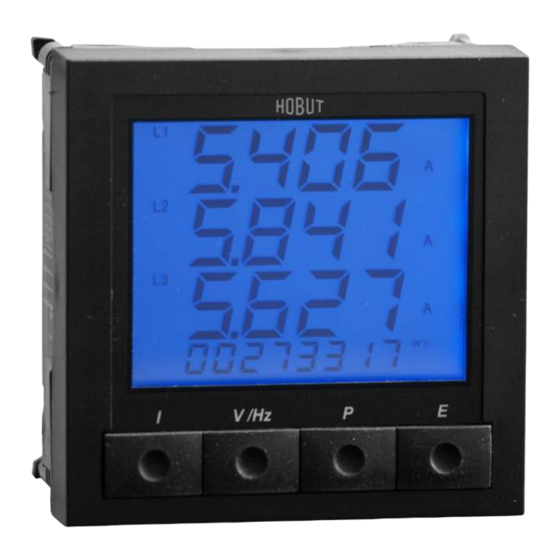
The four front control buttons are used for scrolling up or down through the parameters being measured and displayed. These buttons also allow programming of different current and voltage transformer ratios, demand times, baud rates, etc. The M850-LTHN MultiPower is housed in a 96 mm x 96 mm DIN style case. The case is constructed of black polycarbonate and is compliant with UL 94VO. -
Page 6: Model Number Plus Option Codes
But if the ratio change was 800/1A, the M850-LTHN would have to be returned to the factory to have the internal circuits changed to 1 Amp at a cost or purchase a new unit. Warning: The secondary of a current transformer must never be allowed to be in an open circuit condition when the primary is energized. -
Page 7: Measured Values
1.1.3 Measured Values Phase Power L-L (V) Instantaneous Demand Amp Phase to Neutral L-N (V) Instantaneous Demand Apparent Power Phase Current (I) Maximum Demand Amps Frequency (Hz) Maximum Demand Active Power Active Power (W) Maximum Demand Apparent Power Reactive Power (VA) Maximum Active Power Demand Active Energy (W.h.) Maximum Reactive Power Demand... - Page 8 Insulation Installation Category: III (480V,AC L-L) Degree of Pollution: Rated Impulse Withstand IEC 60947-1-V imp: 4kV Voltage: Meters Front: Class II Electrical Security: IEC 61010-1 Environment Working Temperature: F to +140 F (0 C to +60 C) (Extended ranges available) Storage Temperature: F to +185 F (-40...
- Page 9 Ethernet module: Supported Protocols: When used with M850-THD Telnet Port 23 MODBUS TCP/IP Port 502 MODBUS TCP Port 4000 HTML Port 80 A cross-over CAT5 Ethernet cable should be used if the network card does not automatically swap lines to suit the cable’s terminations.
-
Page 10: Compliance
Compliance Compliance Standard Applicable to ANSI C37.90A Insulation Surge Withstand BS4753 Insulation Protection, Class II BS4889 General Construction BSEN601010 Safety BSEN60688 General Construction CISPR11 Class A Conducted and radiated emissions compatibility DIN 57411 Insulation Protection, Class II EN 55020 HF Insulation Impulse Test IEC 1010 Safety... -
Page 11: Chapter 2: Mechanical Installation
Chapter 2: Mechanical Installation Introduction / Cut-out Details The M850-LTHN MultiPower is designed for panel mounting and uses a standard 96mm x 96mm DIN case. It fits into standard 96mm DIN openings. Panel Cutout and Dimensions of the M850-LTHN & M850-LTHN-RS-PO (shown in mm) Panel Mounting Procedure To install the M850-LTHN:... -
Page 12: Terminal Block Notes
Terminal Block Notes: Terminal screws are tightened using a flat-head screwdriver. It is recommended that the terminal screws be tightened by hand initially. When re-tightening with pneumatic screwdrivers, use a maximum torque of 0.5-1.0 Newton meters (Nm) or 1.1 in.-lbs. Force greater than the recommended tightening torque will damage the terminal block and connection. -
Page 13: Chapter 3: Electrical Installation
Chapter 3: Electrical Installation Considerations When Installing Meters It is recommended that wherever possible any/all equipment be installed, serviced, repaired or replaced in de-energized conditions. If this is not possible, then installation of the M850-LTHN must be performed by qualified personnel who follow all required safety precautions and procedures. -
Page 14: Voltage And Power Supply Connections
Voltage Current and Power Supply Connections All inputs are connected to the back of the unit via high contact pressure terminal blocks. The connectors accommodate up to AWG#12 / 2.5mm wire. APPLICABLE ELECTRIAL SYSTEMS The M850-LTHN can be used on the following measured systems without any changes apart from wiring and programming configurations: Single Phase 3 Phase, 3 Wire balanced... -
Page 15: Terminations To Meter
Terminations to Meter CURRENT TRANSFORMER CONNECTIONS: Internally the M850-LTHN-RS-PO is either a 5 Amp, 1 Amp or 0.333mV rated. Current transformers must be attached externally. The current circuit is designed for connection to the secondary of external current transformers. These transformers should conform to at least Class 1 accuracy, or preferably ANSI C57.13 or equal. Warning: The secondary of a current transformer must never be allowed to be in an open circuit condition when the primary is energized. -
Page 16: Chapter 4: Communications
Chapter 4: Communications Communications Overview The M850-LTHN-RS-PO has an internal RS485 (MODBUS) communications card, as well as a pulsed output relay. The RS485 communications card enables remote reading of up to 32 M850 units on a single 2-wire bus using the MODBUS protocol. -
Page 17: Using The Communications Software
The device you have selected, will come with software or will be just plug and play, either way, follow the instruction provided to install all drivers necessary to operate the device. Multiview and Multilog software: 1. Download and install the files http://www.hobut.co.uk/images/HOBUT-MViewV02.zip for MultilogV02 http://www.hobut.co.uk/images/MLogV2002.exe for MultiView. - Page 18 The first tab on the Project set up screen allows all the details of a project to be entered. Some of this can be displayed beneath the graphs. The second tab is used to enter the logging parameters of a project to be entered. The Graph Setup screen enables the user to tailor the graph screens.
-
Page 19: Measurement Logging With Multiview
Measurement Logging with MultiView The measurements displayed in the Monitor/Log area of the MultiView program can be captured and saved to files. A choice of 1 to 6 channels can be selected from the drop-down menu, ‘Measurements’. The order of the registers can be altered to make this set up more effective. - Page 20 Response Time = 300ms, Logging Period = 3, Measurements = 4 Triggering occurred on V1 (over) and all measurements logged. May 16 2003 13:53:41 242.0 242.0 242.0 500.0 May 16 2003 13:53:42 242.0 242.0 242.0 500.0 May 16 2003 13:53:43 242.0 242.0 242.0...
-
Page 21: Network Description
Network Description In this section, we use the following words to describe: NODE: a network device, typically a PLC, PC, instrument or transducer. MASTER: a NODE which controls the protocol of a MASTER-SLAVE network. SLAVE: a node which responds to specific requests from a MASTER node. ADDRESS: a node's unique network identifier in the range of 1-247. - Page 22 See Appendix A for the MODBUS Registers. These list the parameters with the MODBUS equivalent address and its address within the M850-LTHN-RS-PO. Any data requested that isn't applicable to the Type & System column, will return the value -ve infinity (FFFFFFFFh). The order can be altered using the MultiView Program supplied or by a suitable SCADA program.
-
Page 23: 3X Registers
((MODBUS implied 3x start address - 30001)*2) for the register start address. (Number of measurements required x 2) for registers required. Packet Structure A packet of data transmitted by a MASTER node will look something like the following example: [Address (1 byte)][Function Code (1 byte)][Register Start Address (2 bytes)][Number of Registers Required (2 bytes)][CRC error check (2 bytes)] Request the measured voltages of a meter (MODBUS addresses 30004 to 30006) from SLAVE 2. - Page 24 Internally, the M850 3X Registers are duplicated in the 4X Register area from address 41001, (internal register offset 2001 (07D1h)). This allows PLCs that can’t read floating point data in the 3X area to retrieve the measurements from the 4X area. See Appendix A for a list of the MODBUS Registers. The registers are listed with their MODBUS addresses •...
- Page 25 e.g. To read the 41 MODBUS registers in node 23h a request to send 21 (15h) registers is made: [23h][42h][0000h][0015h][CRC(2 bytes)] A sample write packet will look like this: [Node][41][start address(always 0000h)][No. of Double Registers][Data length in bytes] [REGISTERS][CRC(2 bytes)] e.g.
- Page 26 Send relay channel’s parameters (function 103) Send 8, 16 byte structures. Note: Only the first two structures are used by the M850 Format: [node number][67h][register start(2 bytes)][number of registers(2 bytes)][number of bytes] [<-8, 16 byte structures + 1 relay actions + 1 padding byte (130 (82h) bytes of data)->][crc(2 bytes)] One of the 8, 16 byte structures to send to the M850 is defined below.
- Page 27 One of the 8, 16 byte structures read from the M850 is defined below. Byte # Name Usage Type unsigned char unsigned char Energy Relay (254) char char char char unsigned int unsigned int char ID value (15 = W.h, 16 = VAr.h) char char Physical Relay Number of attached relay...
- Page 28 2nd Byte: A NULL byte for padding. Function 104 Coding Example Request relay(s) channel's parameters from node 1. All eight structures are requested but only the first two are valid. Format: [node address][68h][register start(2 bytes)][number of registers(2 bytes)][crc(2 bytes)] [01][68][0000][0041][A033] Returned relay(s) channel's parameters Format: [node number][68h][register start(2 bytes)][number of registers(2 bytes)][number of bytes][<-8 structures + 1 relay...
-
Page 29: 4X Registers
4.5.2 4X Registers The registers are listed with their MODBUS addresses. See Appendix A for a complete list of 4X Registers. The data held at these addresses are Read-Only, Write-Only or Read+Write, as indicated below. 4X registers are read using function 03h and written using function 10h. A sample write packet will look like this: [Node][10][start address][No. -
Page 30: M850-Lthn-Rs Communications And Programming Overview
Read relay channel’s parameters (code 104) Requests 8, 16 byte structures representing the parameters for the 8 conditions that can be attached to each relay installed. NOTE: only the first two channels are applicable but all 16 will be read. Exception Codes A normal response from a slave is the echoing of the function code and the supplying of the data that is requested. - Page 31 A typical communication 'packet' will be in the form: [Node Address] [Function] [Byte count, Data etc.] [Error check] Because MODBUS is a word (2 byte) orientated protocol, floating point (4 byte) register numbers are counted in multiples of two. register 1 = start address 0 register 2 = start address 2...
-
Page 32: Chapter 5: Using The M850-Lthn Meter
Chapter 5: Using the M850-LTHN Meter Introduction All units can be fully programmed by the factory but there are many features that can be programmed by the User to suit individual applications and needs. Programmed values and parameters are stored in non volatile memory and are therefore retained in power down situations. -
Page 33: Display Screens
5.1.2 Display Screens Each screen is displayed by pressing one of the four front panel buttons: ‘I’ for Current ‘V/Hz’ for Voltage and Frequency ‘P’ for Power and ‘E’ for Energy Display Screens of the M850-LTHN Press the ‘I’ button to access measurements on Current. One press of the button displays line currents; two presses of the button displays neutral current;... -
Page 34: Settings Menu Including Abbreviations As Seen On Screen
LCD Brightness adjustment: It is possible to adjust the brightness on the M850-LTHN display by: 1. Hold down the two center buttons (‘V/Hz’ and ‘P’) simultaneously on the front panel. 2. The brightness level will adjust as the buttons are held down. 3. -
Page 35: Supply (Supp) Sub-Menu
The following abbreviations are displayed on the sub-menu screens when the M850 is in Setting Menu mode: Display Indicates ADDR Address for communications ADJ (VAr) Adjust Pulses (VAr) ADJ (W) Adjust Pulses (Power) BAUD Baud Rate CNCL Cancel any changes CODE Password Code COMMS... - Page 36 The system’s type is selected from the following list: Unbalanced 1 phase 2 wire 3 phase 3 wire 3 phase 4 wire 1 phase 3 wire Balanced 3P3B 3 phase 3 wire 3P4B 3 phase 4 wire When entering data, numbers can be entered into the unit in the following way: See Appendix C.2 for the SUPPLY programming screens.
-
Page 37: Communications (Comms Rs485) Sub-Menu
5.2.2 Communications (485) Sub-Menu This sub-menu contains screens for monitoring: Communications Address; Baud Rate; Stop Bits; Parity; Endian; Lock; Canceling and Confirming actions within this section. When using the plug-in RS485 (MODBUS protocol) option, the network settings can be detected and the unit configured automatically. -
Page 38: Demand (Dt) Sub-Menu
When entering data, numbers can be entered into When only fixed data can be entered, you can the unit in the following way: select the values from the list: Press ‘E’ to scroll through the list. Press ‘I’ to select the displayed value Press ‘I’... -
Page 39: Energy (Engy) Sub-Menu
5.2.4 Energy (ENGY) Sub-Menu This sub-menu contains screens for: Adjust Pulses (W); Adjust Pulses (VAr); Reset; Canceling and Confirming actions within this section. There are two energy accumulators in the unit: Import Power and Import VAr. Modifications to the pulses per hour rate can be done through this sub-menu. -
Page 40: Relay (Rlay) Sub-Menu
5.2.5 Relay (RLAY) Sub-Menu This sub-menu contains screens for: Relay Type; Pulse Length; Pulses per Hour; Canceling and Confirming actions within this section. The Pulsed Output option of the M850-LTHN-RS-PO can operate as W.h. or VAR.h. types. The principal relay can be set up in this sub-menu. -
Page 41: Code (Code) Sub-Menu
5.2.6 Code (CODE) Sub-Menu This sub-menu contains screens for: Edit; Set; Canceling and Confirming actions within this section. See Appendix C.6 for the CODE programming screens. Within this sub-menu, password protection can be set to prevent accidental and unauthorized tampering of the M850-LTHN’s settings. -
Page 42: Chapter 6: Configuring The M850-Lthn Using The Front Panel
Chapter 6: Configuring the M850-LTHN Using the Front Panel System Type Programming 1. Press “I” & “E” simultaneously and hold for 5 seconds. The unit is now in setup mode. The screen will change to “SUPP”. (Most times, the display goes through “SUPP” directly to “SYSA”. This is due to a timing problem with releasing the buttons.) 2. -
Page 43: Configure Ct Ratio Settings
Configure CT Setting Internally the M850-LTHN MultiPower is fitted to with either 5 Amp (as standard), 1 Amp and 0.333mV are optional. The current circuit is designed for connection to the secondary of external CT. These transformers should conform to at least Class 1 as per BS7626 (IEC 185) or equivalent. The secondary of these external transformers must have the same nominal current input as that specified on the data label on the M850-LTHN. -
Page 44: Configure Vt Ratio Settings
10. Press “E” until “END” is displayed. Then press “I”. Now you are out of programming mode. 11. Check the resulting display on the meter for voltage and current to see that the desired numeral is displayed and the decimal is in the proper location. 12. -
Page 45: Vt Ratio Programming
6.3.1 VT (or PT) Ratio Programming 1. Press “I” & “E” simultaneously and hold for 5 seconds. The unit is now in setup mode. The screen will change to “SUPP” 2. Press “I” button once. The screen displays “SYSA”. 3. Press “E” button once. The screen displays “UPr1”. 4. -
Page 46: Configure Max Demand Time Setting
18. Check the resulting display on the meter for voltage and current to see that the desired numbers are displayed and the decimal is in the proper location. 19. If not, repeat procedure starting with step 1 and check that the proper numbers are programmed into the meter. -
Page 47: Max Demand Time Setting
6.4.1 Max Demand Time Setting In this example, the maximum Demand Time setting will be made to 30 minutes. Here are the programming instructions to set the M850-LTHN to that setting: 1. Press “I” & “E” simultaneously and hold for 5 seconds. The unit is now in setup mode. The screen will change to “SUPP”... -
Page 48: Appendix A: Modbus Registers
Appendix A: MODBUS Registers 3X and 4X Registers *= Special Build ***= Not supported M 8 5 0 - L T H N M u l t i P o w e r I n s t a l l a t i o n a n d O p e r a t i o n M a n u a l Page 48... -
Page 49: Register Addresses And Modes
Register Addresses and Modes M 8 5 0 - L T H N M u l t i P o w e r I n s t a l l a t i o n a n d O p e r a t i o n M a n u a l Page 49... -
Page 50: Appendix B: M850-Lthn Quick Start Guide
Appendix B: M850-LTHN Quick Start Guide M 8 5 0 - L T H N M u l t i P o w e r I n s t a l l a t i o n a n d O p e r a t i o n M a n u a l Page 50... - Page 51 M 8 5 0 - L T H N M u l t i P o w e r I n s t a l l a t i o n a n d O p e r a t i o n M a n u a l Page 51...
-
Page 52: Appendix C: Programming Screens
Appendix C: Programming Screens Main Menu Screens SUPPLY Programming Screens COMMUNICATIONS Programming Screens M 8 5 0 - L T H N M u l t i P o w e r I n s t a l l a t i o n a n d O p e r a t i o n M a n u a l Page 52... -
Page 53: Demand Programming Screen
DEMAND Programming Screens ENERGY Programming Screens M 8 5 0 - L T H N M u l t i P o w e r I n s t a l l a t i o n a n d O p e r a t i o n M a n u a l Page 53... -
Page 54: Relay Programming Screen
RELAY Programming Screens CODE Programming Screens M 8 5 0 - L T H N M u l t i P o w e r I n s t a l l a t i o n a n d O p e r a t i o n M a n u a l Page 54... -
Page 55: Store Programming Screen
STORE Programming Screens END Programming Screens M 8 5 0 - L T H N M u l t i P o w e r I n s t a l l a t i o n a n d O p e r a t i o n M a n u a l Page 55... - Page 56 Appendix D: Ethernet Plug-In Card Installation (Model M850-THD-ET) and Set-Up M 8 5 0 - L T H N M u l t i P o w e r I n s t a l l a t i o n a n d O p e r a t i o n M a n u a l Page 56...
- Page 57 M 8 5 0 - L T H N M u l t i P o w e r I n s t a l l a t i o n a n d O p e r a t i o n M a n u a l Page 57...
- Page 58 M 8 5 0 - L T H N M u l t i P o w e r I n s t a l l a t i o n a n d O p e r a t i o n M a n u a l Page 58...
- Page 59 M 8 5 0 - L T H N M u l t i P o w e r I n s t a l l a t i o n a n d O p e r a t i o n M a n u a l Page 59...
Need help?
Do you have a question about the MultiPower M850-LTHN-1 and is the answer not in the manual?
Questions and answers