
Related Manuals for Artos 45-700

Summary of Contents for Artos 45-700
- Page 1 Machine Model 45-700 Wire Prepper II Owners Manual 6-119891 Rev. 1.00 Date August 18, 2015 Artos Engineering Company 21605 Gateway Ct. Brookfield, WI 53045 Phone 262 252-4545 Fax 262 252-4544 www.artosnet.com service@artosnet.com...
-
Page 2: Table Of Contents
TABLE OF CONTENTS Customer Safety Notice ........................ 2 Limits of Use ............................ 2 Introduction ............................ 2 Unpacking ............................ 2 Operator Control Features ...................... 3 ON‐OFF Switch .......................... 3 Control Buttons ........................... 3 Standard Features ........................... 3 Set‐up .............................. 4 Putting the Machine to Work ...................... 4 Operating Instructions ........................ 5 Changing Program Settings ...................... 6 Wire Drive Speed: ........................ 6 Storing Wire Batches: ......................... 6 Recall Wire Batches: ........................ 6 ... -
Page 3: Customer Safety Notice
Customer Safety Notice Use of this machine for purposes other than those stated in this manual may result in damage to the machine or personal injury. Use of this machine for purposes other than those stated in this manual may result in damage to the machine or personal injury. WARNING Do not manually disable guard switches or safety covers. Personal injury can result. Do not perform any maintenance on the machine unless the electrical supply to the machine is disconnected. Do not attempt to replace the blades or the feed rollers unless the electric power is disconnected from the machine. Do not operate machine without wearing proper eye protection Do not wear loose clothing or jewelry that might get caught in the operating parts of the machine Do not operate machine in a damp or wet location Do not operate if liquid is spilled on or in the machine Do not operate machine on an ungrounded electrical system Do not alter, modify, or misuse the machine Do not operate machine unless all instructions are read and understood Do not operate machine in a gaseous or hazardous environment. Limits of Use The Wire Prepper® System II is intended for use in a dry indoor working environment. The machine cannot be exposed to liquid spray or mist, damage will result. Circuits should never be removed or tampered with or injury may result. Introduction ... -
Page 4: Operator Control Features
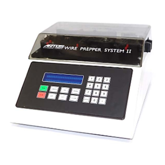
Operator Control Features ON‐OFF Switch ‐ Turns main power on and off. Located on the back of the case. Contains machine fuses. Control Buttons Run—starts machine cycle to measure and cut. Stop—Stops machine cycle. Length—Allows length data to be entered from 0.06” ‐ 9,999.99” Quantity—allows quantity to be entered from 1 ‐ 9,999 pieces. Jog—Activates wire feed motor. Cut—Activates wire cutter. Program—Allows access to wire drive speed, wire batches, length calibration, mode (inches or centimeters), pause time between batches, and demo program. Clear—Used to clear data from display. Enter—Used to enter data once it has been displayed Keyboard— 0 thru 9 keyboard with decimal point for entering numerical data, to set length and quantity. Standard Features Retained Memory—All machine program settings are electronically stored in memory. Preset length and quantity remaining on display will be saved in case of power failure. Wire Alarm—An audio and visual alarm to indicate that the wire is not feeding. Press STOP to turn off alarm. Load new wire or clear jam. Press JOG and CUT to cut excess wire. Press RUN to restart machine. Wire Length Calibration—A program which allows the operator to adjust the cut length for greater accuracy. Mode—(Unit of Measure) A program which allows the Wire Prepper® to measure in inches or centimeters. ... -
Page 5: Set-Up
Pausing Batching—A program which will pause the Wire Prepper® for up to 9 seconds between batches of wire. (i.e. The machine can be set to measure and cut 4,000 wires, and be programmed to pause for 5 seconds after every 50 wires. This permits small bundles for easier handling). Set‐up The Wire Prepper® System II has been set‐up at the factory to cut plastic tubing, heat shrink, and stranded‐copper wire. To cut larger materials, position the slotted guides in place of the feed tubes. This is easily done by removing 2 screws (use ” hex wrench) holding each guide support block and rotating the block 180°. Slotted Guides When cutting round tubing, a slight flattening of the tubing may occur. To minimize this, a release lever screw is provided to limit the closing of the drive wheels. Turn clockwise to lessen the pressure and test for proper feed. The Wire Prepper® System II can also cut SJO cord and multi‐conductor round cable up to ” dia. For this set‐up install optional 0.338 I.D. feed tubes set (LB1448) and 0.375 dia. fixed blade (LB1481). See blade replacement Pg. 8. Putting the Machine to Work ‐ Plug the cord into ON‐OFF switch power module. ... -
Page 6: Operating Instructions
‐ With the machine turned OFF, raise the cover. ‐ Insert tubing in the first guide tube past the encoder rollers until the tubing is touching the feed rollers. While pushing the tubing lightly against the feed rollers, rotate the feed rollers by hand to feed the tubing through the machine and out the discharge chute. ‐ Close cover and turn the machine ON. (Prepper will not run with the cover open). ‐ Press JOG to feed tubing. ‐ Press CUT to cut off excess tubing. ‐ The Wire Prepper is now ready to measure and cut tubing. Operating Instructions Entering Cut Length ‐ Press LENGTH ‐ Enter desired length ‐ Press ENTER Entering Quantity ‐ Press QUANTITY ‐ Enter desired quantity ‐ Press ENTER ... -
Page 7: Changing Program Settings
Changing Program Settings Wire Drive Speed: 10 wire drive speed are available to vary the feed speed of the wire through the machine. Varying the wire feed speed will enable the operator to optimize the machine performance. ‐ Press PRGM (Program). ‐ Press 1 (on keyboard) ‐ Press 1 for slower, 2 for faster ‐ Press ENTER. Storing Wire Batches: A wire batch consists of length, quantity, and other machine settings for frequently repeated production jobs. Up to 99 batches can be programmed by the operator and stored in the machine’s electronic memory. ‐ Enter desired length and quantity on to the display panel. ‐ Press PRGM. ‐ Press 2. ‐ Enter Batch #. ‐ Press ENTER. ‐ Press 2 to store. Recall Wire Batches: ‐ Press PRGM. ‐ Press 2. ‐ Enter batch # to be recalled. ‐ Press ENTER. ‐ Press 1 to recall. ... -
Page 8: Changing Mode
wire, each incremental change in calibration will result in approximately 0.040” change in wire length. For a 100” wire, each incremental change in calibration will result in approximately 0.40” change in wire length. ‐ Press PRGM. ‐ Press 3 for next. ‐ Press 2 for mode. ‐ Press 1 for calibration. ‐ Press 1 for Shorter, 2 for longer, or 3 to reset. ‐ Press ENTER. NOTE: Sample wire should be taken before and after a calibration change is made. Incremental changes will be greater for longer wires. Changing Mode: Mode (unit of measure) allows the machine to measure in inches or centimeters. ‐ Press PRGM. ‐ Press 3 for next. ‐ Press 2 for mode. ‐ Press 1 for Metric (cm) or 2 for English (in). Activate Pause Mode: ‐ Press PRGM. ‐ Press 3 for next. ‐ Press 3 again for next. ‐ Press 1 for PAUSE. ‐ Press 1 again to enter pause mode. ... -
Page 9: Fuse Replacement
located on the front of the unit (lower right corner); replace the fuse cartridge making sure the voltage selection arrow aligns with the arrow located in the front of the unit. Voltage Selection Arrow Fuse Replacement Remove the fuse cartridge using a small blade screwdriver or similar tool. Replace two 3 AMP Slo‐Blo fuses, and insert the fuse cartridge back into the unit; making certain the PROPER VOLTAGE SELECTION ARROW aligns with the narrow located on the front of the unit. Maintenance Periodic oiling of the blade arm is required. Two drops of oil where the blade arm pivots. ‐ The frequency will depend on usage. OIL HERE Periodic cleaning of the encoder and drive rollers when build‐up appears will help ‐ assure accurate machine operation. ... -
Page 10: Blade Replacement
Encoder Drive Rollers Blade Replacement 1. Unplug the unit. Remove discharge chute. Remove blade retaining clip. Lift out movable blade. Remove the screws holding the fixed blade. ... -
Page 11: Encoder Disassembly
NOTE: Remove screws from blade block (use ” hex wrench) and rotate the block a few degrees to access lower left blade screw. 6. Remove the fixed Blade. NOTE: This blade can be rotated 180° to use other cutting edge. Encoder Disassembly 1. Remove the top plate assembly and place it upside down on the work bench. 2. Use a flat blade screwdriver to turn the lock to the position with one dot. This will expose a hole in the side where a hex wrench can be inserted. ... - Page 12 Hole 3. Insert a 0.034” hex wrench into the body of the encoder insuring that it is properly seated into the code wheel hub set screw. You will have to turn encoder roller to find this position. 4. Loosen the set screw by turning counter clockwise. 5. Remove the encoder form the encoder base by inserting a small blade screwdriver at the snap locations and twisting slightly. ...
- Page 13 Snap location Snap location 6. Gently remove the plastic code wheel retainer. 7. Remove the hex wrench. 8. Remove the code wheel, clean with contact cleaner. 9. Install the code wheel and plastic code wheel retainer back into the encoder housing. 10. Insert the 0.034” hex wrench to engage the code wheel hub set screw. Encoder is now ready for assembly to top plate. ...
-
Page 14: Encoder Assembly
Encoder Assembly 1. Snap the encoder body onto the top plate locking all 4 snaps. 2. With the 0.034” hex wrench properly seated into the code wheel hub set screw apply a downward force on the end of the hex wrench. This sets the code wheel gap by leveling the code wheel hub to its upper position. 3. While continuing to apply a downward force, rotate the hex wrench in the clockwise direction until the hub set screw is tight against the wheel shaft. 4. Remove the hex wrench by pulling it straight out of the encoder body. 5. Use the center screwdriver slot, or either of the two side slots, to rotate the encoder cap dot clockwise form the one dot position to the two dot position. ... -
Page 15: Drive Wheel Replacement
6. Recheck encoder rollers for free movement. 7. Separate wheels by hand and rotate wheel. 8. The encoder is ready for use. Drive Wheel Replacement 1. Remove the 3 screws from the spring pressure on drive wheels and the retaining block. Retaining Block 2. Remove the screw (#10‐32) (use “ hex wrench) holding drive wheel to motor shaft and remove drive wheel/gear assembly. ... - Page 16 3. Remove the 2 (#8‐32) button head screws then remove the wheel top plate and spac 4. Remove drive wheel/gear assembly. 5. Remove gear and spacer from each drive wheel. 6. Install gear and spacer onto new drive wheel, using the fixture pin (LB1429) provide with machine. Tighten screws securely. ...
-
Page 17: Trouble Shooting
NOTE Fixture pin is necessary to assure alignment 7. Reassemble drive wheels and springs. Trouble Shooting “Wire Alarm” Sounds Check for wire jams at machine or de‐reeler. Check wire straightener adjustment (wire straightener is an optional accessory). Pressure on wire may be too high. Check encoder wheel from free rotation. Push spring loaded wheel away from encoder wheel, then spin encoder wheel. It is mounted on ball bearings and should rotate freely. If restriction is felt, see Encoder Assembly/Disassembly procedure. Make sure that the first wire feed tube is not rubbing against the encoder wheels. Wire Length Not Accurate Check wire length calibration. The number in the lower right corner of the calibration viewing screen should be close to 0.025. If necessary, press 3 to reset wire calibration (should reset to 0.025). Check de‐reeler for smooth operation. An easy check is to hand feed the wire to the machine so that there is no restriction. If the cut wires become accurate, then the problem is in the de‐reeling. Check encoder rollers for free movement, or foreign matter. Check encoder code wheel for foreign material in windows. To do this, it is necessary to disassemble the encoder from the top plate. Refer to “Encoder Disassembly” in this manual. -
Page 18: Display Reads "Cutter Malfunction, Machine Will Not Cut
Display Reads “Cutter Malfunction, Machine Will Not Cut” Remove discharge chute, check for obstruction at cutting blade. Remove top plate assembly from case, rotate cutter motor arm, and check for jammed cutter mechanism. Check cutter motor electrical connections. Machine Will Not Function, All Switches Do Not Work Turn the machine off and then back on to reset the machine electronics. Cutters Cycles Continuously Check cutter home sensor switch located under the top plate. When the cutter arm is in the home position, the steel vane should be inside the switch slot. Adjust the steel vane so that the cutting blade clears the cutting hole when in the home position. Drive Wheel Operation is Rough Check for debris caught in drive gears. ... -
Page 19: Cutters Do Not Cut Material Cleanly
Remove center tubing guide assembly. After removing debris, replace all parts. Cutters Do Not Cut Material Cleanly Check cutting blades for sharpness. NOTE: Fixed blade can be rotated 180° to use other cutting edge. See Blade Installation. Increase pressure at cutting blades by turning blade clip set screw clockwise ” to ” turn (use 0.05 hex wrench). Make a sample cut to assure complete clean cutting. Wire and Tubing Cuts are Not Square Select feed tubes sized closer to wire diameter (see “Accessories” section). Use optional round hole fixed blade (see “Accessories” section). Tubing Crushed by Rollers Adjust released lever screw to limit the closing of the drive rollers. Turn clockwise to lessen pressure. NOTE: If drive rollers do not close sufficiently onto the tubing the “Wire Alarm” may sound. Optional light force springs are available for encoder and drive wheels. See Replacement Parts Lost for part numers. ... -
Page 20: Accessories
Accessories Support set Description Part # Feed Tube Support Set LB‐1438 for ¼” O.D. (set of 3) ” O.D. Feed Tubes (set of 3) Description Part # 0.180 I.D. LB‐1439 0.152 I.D. LB‐1440 0.120 I.D. LB‐1441 0.084 I.D. LB‐1442 0.060 I.D. LB‐1443 ” O.D. Feed Tubes (set of 3) Description Part # 0.265 I.D. LB‐1444 0.281 I.D. LB‐1445 0.312 I.D. LB‐1446 0.344 I.D. LB‐1447 0.388 I.D. LB‐1448 ... - Page 21 Premium Wire De‐Reeler (Part # 45‐712) For use with Wire Processing equipment and 6” – 16” Dia. wire reels. Wire Straightener (Part # 45‐713) For use with Wire Prepper® System II. Fastens to Wire Prepper®. ...
- Page 22 ...
- Page 23 ...
- Page 24 ...
- Page 25 ...
- Page 26 ...
Need help?
Do you have a question about the 45-700 and is the answer not in the manual?
Questions and answers
quote: s/n 45-700 201306032 • Fuse 3 amp • 45‐721 Urethane Drive Wheels • 45‐722 Steel Knurled Drive Wheels • Blade 1434