Table of Contents
Advertisement
Advertisement
Table of Contents

Summary of Contents for Tranax Mini-Bank 1500
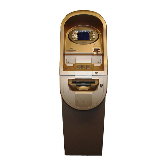
- Page 1 OPERATOR MANUAL Mini-Bank 1500™...
-
Page 2: Table Of Contents
Table of Contents Operator Manual TABLE OF CONTENTS 1. INTRODUCTION 1.1 Features 1.1.1 About the Mini-Bank 1500™ 1.2 Specifications 1.2.1 Mini-Bank 1500™ Specifications 1.2.1.1 Dimensions 1.2.1.2 Component Locations 1.2.1.3 LCD & Customer Keypad 1.2.1.4 Cash Dispensing Unit 1.2.1.5 Receipt Printer 1.2.1.6... - Page 3 Table of Contents Operator Manual 3.5 Transaction Setup 3.5.1 Dispense Limit 3.5.2 Denomination 3.5.3 Fast Cash 3.5.4 Low Currency Check 4. OPERATION 4.1 Opening and Closing 4.1.1 Mini-Bank 4.1.1.1 Opening the Security Door 4.1.1.2 Closing the Security Door 4.1.1.3 Opening the Front Panel 4.1.1.4 Closing the Front Panel 4.1.1.5...
-
Page 4: Features
1.1.1 ABOUT THE Mini-Bank 1500™ The Tranax Mini-Bank1500™ represents the absolute best value in retail ATMs. The Mini-Bank 1500™ inherits the unsurpassed reliability and quality of the MB-1000 and 2000. An eye-catching design coupled with numerous enhancements to ensure ADA, TDES and VISA PIN security compliance, makes the Mini-Bank 1500™... -
Page 5: Specifications
Introduction Operator Manual 1.2 SPECIFICATIONS Mini-Bank 1500™ SPECIFICATIONS 1.2.1 Dimensions Fig. 1 Mini-Bank Dimensions WEIGHT: 269 lbs. Doc. No. 101205... -
Page 6: Lcd & Customer Keypad
Introduction Operator Manual 1.2.2 LCD & Customer Keypad Fig. 3 LCD & Customer Keypad Screen Size: 6” Mono/Color (optional) Resolution: 320 x 240 Display Characters: 40 x 15 (Standard Characters) 8 Menu Keys KEYPAD Lab Certified VISA compliant EPP (Encrypting Pin Pad) 10 Alphanumeric, 3,4, CANCEL, CLEAR, ENTER, BLANK Keypads Each Keypad has integral raised Braille symbols Voice Guidance Port... -
Page 7: Cash Dispensing Unit
Introduction Operator Manual 1.2.3 Cash Dispensing Unit Cash Dispensing Unit (Standard drawer type) CASH DISPENSING UNIT Dispensing Speed: 4 notes/second Capacity of 1100 new notes per tray (standard dispenser) Capacity of optional dispensers* depending on model. Reject Bin with capacity of 200 notes Low Level Cassette Detection (not available in 1000 note cassette configuration) Double note detect module *Optional dispensers include:... -
Page 8: Receipt Printer
Introduction Operator Manual 1.2.4 Receipt Printer Receipt Printer RECEIPT PRINTER Thermal line printer 36 characters/line Semi-automatic roll paper setting Motorized front push rollers PAPER SPECIFICATIONS One sided thermal paper Factory paper is thermal side out (but either way will work) 7.0 inch outside diameter roll 3.125”... -
Page 9: Main Control Board
110/220 VAC ± 10%, 50/60 Hz, 250 Watts POWER CONNECTIONS For warranty purposes, the Mini-Bank 1500™ series ATM must be connected to a dedicated power circuit. This circuit must consist of line, neutral, and ground leads connected directly to the power circuit breaker panel. This circuit should not be shared with any other equipment. -
Page 10: Warranty/Service
ATM owner. Tranax will only honor the extended warranty of a MiniBank ATM that is registered in the Tranax Extended Part Replacement (EPR) warranty program. -
Page 11: Installation
Locate the Anchor Template in the bottom of the vault. Use the template to drill the appropriate sized holes for the anchors you will be using. (Anchors are not included). Tranax does not recommend a particular size or type of anchor as each installation is different however maximum anchor diameter is ½... -
Page 12: Hardware Setup
115V. The default setting should be 115V Step 2 Verify that the telephone line to be used for the ATM is in proper working order. Tranax recommends the use of shielded (CAT5) phone line in locations with close proximity to other appliances. Step 3 Open the security door and remove any shipping materials and note any warning or installation instructions. - Page 13 Section 2: Installation Operator Manual Step 6 Open the top of the ATM. Place the receipt paper in the Receipt Printer. The paper prints only on one side (shiny side) always check the roll when you install paper. Place the roll so that the coated side (shiny side) will be facing up. See page 4.12 for paper loading instruction.
-
Page 14: Programming
Passwords are very important to maintaining security for your ATM. Your dealer/distributor will provide you with default password information. NOTE: Tranax Technologies, Inc. highly recommends changing your passwords from default as soon as possible. Passwords MUST be 6 digits in length, use of anything other than a 6 digit password may cause the passwords to revert back to factory default. - Page 15 Section 3: Programming Operator Manual Step 3 Shown the left is the complete Operator Function menu, depending on which password you entered (operators, service, master) you may not see certain functions. For example, if you use an operator password you will not see the Host Setup button, as you will not have access to that menu.
-
Page 16: When An Error Occurs
Section 3: Programming Operator Manual 3.1.2 WHEN AN ERROR OCCURS Step 1 When an error occurs, please press “CANCEL, CLEAR and ENTER” simultaneously, and then press 1, 2, 3 keys in order. NOTE: If the machine goes out of service, the error code will not always appear on the screen. - Page 17 Press and hold while powering on ATM: F6: Clear NVRAM F7: Download Fig. 1 Mini-Bank 1500™ keypad and LCD display NOTE: LCD Keypads are no longer used for Master Key letters. Please see addendum included with this manual. Shift Status Space...
- Page 18 Section 3: Programming Operator Manual How to enter data with the keypad 1. The Keypad Character Table (Fig. 2) will appear on the bottom of the screen if keypad input is required. 2. F5 key toggles between alphabetic or numeric mode. Default is alphabetic mode. 3.
-
Page 19: Key Management
Section 3: Programming Operator Manual 3.2 HOST SETUP The Host Setup menu provides access to the parameters necessary to connect the ATM to the processor. Master Password is required to access most of these options; however Service password allows basic access for troubleshooting purposes. 3.2.1 KEY MANAGEMENT Access to Key Management requires entering a “Secure Mode”... - Page 20 Section 3: Programming Operator Manual Successful entry of both passwords will grant access to the Key Management screen. From the moment the Key Management area is entered, a 5 minute timer begins. At the end of 5 minutes, regardless of what you are doing (entering a master key for example) the Key Management area times out and you will be taken back to the Host Setup menu.
- Page 21 Section 3: Programming Operator Manual NOTE: Some processors only provide one 16-digit number in which case you enter all 0’s or 1’s for the second part. Please contact your dealer or processor for questions regarding your Master Keys. CHANGE PASSWORD This allows you to set each part of the “Secure Mode”...
-
Page 22: Set Host Telephone Number
(to correct any mistakes, or edit existing numbers). Step 5 Tranax always recommends using a dedicated, data-quality phone line for all ATM installations, however if you are using a phone line that is dialing out through a PBX type system (where you dial a number for an outside line), then you may insert commas ( , ) to create a pause between digits. -
Page 23: Set Terminal Id / Routing Id Number
Section 3: Programming Operator Manual 3.2.3 SET TERMINAL ID / ROUTING ID NUMBER Step 1 From the Host Setup Menu, go to Terminal ID or Routing ID. Terminal ID number is provided by the processor and is individual for your ATM. It identifies your ATM on the network and any transactions done on your machine will be linked to that number. -
Page 24: Connect Timer
3.2.6 REMOTE MONITOR Remote Monitoring is the ability to dial into your ATM and send or retrieve information using Tranax Remote Management Software (RMS). RMS EN/DISABLE This will allow the ATM to be monitored remotely. -
Page 25: Trial Day Total
Section 3: Programming Operator Manual REMOTE PHONE #1, #2 This is the number the ATM will call if there is an out of service condition. Press the button for either number and enter the number for the computer you want the ATM to call. - Page 26 Section 3: Programming Operator Manual 3.2.8 HOST PROCESSOR MODE Host Processor selection changes the communications protocol to specifically match your particular processor. In most cases this is set at the factory when your machine is ordered, however in the event that the machine needs to be reprogrammed for a new processor, it may be necessary to change the processor mode.
-
Page 27: The System Setup Menu
Section 3: Programming Operator Manual 3.3 THE SYSTEM SETUP MENU 3.3.1 SET CLOCK The Set Clock menu allows you to set the clock built into the ATM to the appropriate date and time. You should set this for local time in the area the machine is to be installed. -
Page 28: Iso 1,2,3 En/Disable
Section 3: Programming Operator Manual 3.3.3 ISO 1, 2, 3 EN/DISABLE The ISO Tracks are the three tracks available for the card swipe head to read. The ATM is defaulted to only read from Track #2. This parameter should not be changed. -
Page 29: Change Passwords
Section 3: Programming Operator Manual 3.3.5 CHANGE PASSWORDS The ATM uses three passwords to provide security to the operator menu system. These are Operator, Service and Master. • Operator Password (allows access to basic menu structure) • Service Password (allows access to basic and diagnostic menus) •... -
Page 30: Modem Setup
INITIAL STRING This is the command line that the modem uses to communicate. This should not be changed from factory default. Changing the modem string can cause communications problems. Factory Init String for Mini-Bank 1500™ = AT&F&Q6+MS=V22B Doc. No. 101205 3.17... -
Page 31: Modem Test
The downside to this is if something else is answering then the Remote Management Software (RMS) will not be able to connect unless that device is turned off. Tranax does not recommend setting this count higher than 4 rings if you intend on connecting with RMS. -
Page 32: Customer Setup Menu
Section 3: Programming Operator Manual 3.4 CUSTOMER SETUP MENU The Customer Setup menu controls surcharge information, BIN lists, receipt options, advertisements and keypad lighting. 3.4.1 CHANGE MESSAGE The Messaging options for the ATM are a welcome message and a receipt header message. - Page 33 Section 3: Programming Operator Manual WELCOME MESSAGE Once you have selected Welcome Message from the Change Message Menu, you will be prompted with the following screen. Using the numbers on the keypad press the number above the letter you wish to select until that letter is highlighted by the white box.
-
Page 34: Bin Lists
Section 3: Programming Operator Manual 3.4.2 BIN LISTS BIN numbers are card numbers that you have preset with your processor to not be surcharged. You must set this up with your processor, who will then give you numbers to enter in the list. These numbers will reference cards that you wish to not be charged a surcharge for transactions. -
Page 35: Optional Function
Section 3: Programming Operator Manual 3.4.3 OPTIONAL FEATURES The ATM offers 2 optional functions to improve performance and keep the ATM functional in the event of a paper problem (jam, out of paper etc.) These are Pre- dialing and Selective Receipt. PRE-DIALING With this feature enabled the ATM will begin to dial out to the processor as soon as a customer swipes their card. -
Page 36: Surcharge Mode
Section 3: Programming Operator Manual 3.4.5 SURCHARGE MODE The Surcharge menu displays the current rate at which customers are charged per transaction, the person or account that the surcharge funds are sent to and whether or not the option to surcharge is enabled or disabled. The information programmed here must match the information given to the processor at the time the account was created. - Page 37 Section 3: Programming Operator Manual SURCHARGE OWNER The surcharge owner can be up to 25 characters long. This owner name will appear at the bottom of each transaction receipt. To enter the surcharge name press the surcharge owner button and then select a character table by pressing the button labeled ALPHA.
-
Page 38: Advertisements
Operator Manual 3.4.6 ADVERTISEMENTS The Mini-Bank 1500™ is capable of displaying up to 7 graphic screen advertisements. These ads are created on a computer and then downloaded into the ATM either directly at the ATM using a laptop and a special download cable (available from your dealer) or through the phone line using the Remote Management Software (RMS). - Page 39 Section 3: Programming Operator Manual Step 2 Next choose Primary Screen, this will give you the option of 4 screens, each of these primary screens can have a coupon. NOTE: The coupons are completely independent of on screen advertisements or whether or not they are enabled or disabled.
-
Page 40: Transaction Setup
Section 3: Programming Operator Manual 3.5 TRANSACTION SETUP 3.5.1 DISPENSE LIMIT The dispense limit is the maximum amount of money a customer can withdraw in a single transaction. The ATM will dispense a maximum of 40 notes per transaction. So the dispense limit can be a maximum of 40 times the denomination of notes your using. - Page 41 Section 3: Programming Operator Manual The Denomination is the type of bill that each cassette will be dispensing. The ATM offers a second cassette as an option. This second cassette can be programmed to dispense notes, it can also dispense a preset number of bill sized coupons with each transaction and finally it can dispense a “value coupon”, where you would set the value of the coupon and the customer could purchase this using their card.
- Page 42 Section 3: Programming Operator Manual TYPE OF NON-CASH If you are going to be selling a non-cash item (for example: a voucher for stamps). This is where you will set the name of the item to be sold. The text you enter for this will appear as an option to the customer after they swipe their card and enter the PIN.
-
Page 43: Fast Cash
Section 3: Programming Operator Manual 3.5.3 FAST CASH Fast Cash amounts are presented to the customer if they choose a Withdrawal transaction. These amounts appear on screen as an easy method of selecting how much cash they wish to withdraw for that transaction. The amounts must be multipliers of the denomination amount. -
Page 44: Operation
Section 4: Operation Operator Manual SECTION 4: OPERATION 4.1 OPENING AND CLOSING 4.1.1 Opening the Security Door Step 1 Turn the Security Cover key clockwise to open the Security Cover. Step 2 To unlock the Combination Lock, refer to Section 4.1.6. Step 3 Turn the security Door Handle counter- clockwise;... -
Page 45: Closing The Security Door
Section 4: Operation Operator Manual 4.1.3 Closing the Security Door Step 1 With the security door handle turned counter-clockwise, close the security door and turn the security door handle clockwise until it is locked. Make sure one more time that the security door is closed. NOTE: The handle must be completely vertical before turning the lock. -
Page 46: Opening The Front Panel
Section 4: Operation Operator Manual 4.1.4 Opening the Front Panel Step 1 Insert the Front Panel key and turn it clockwise. Step 2 With the Front Panel key turned, pull the Front Panel outward. Doc. No. 101205... -
Page 47: Closing The Front Panel
Section 4: Operation Operator Manual 4.1.5 Closing the Front Panel Step 1 Push the Front Panel slowly until it is locked back in place. Step 2 Turn the Front Panel key counter-clockwise until the Front Panel key can be taken out. Doc. -
Page 48: Operating And Changing The Combination Lock
Section 4: Operation Operator Manual 4.1.6 Operating and Changing the Combination Lock (non-electronic) Changing Index Before operating the lock or changing the combination, READ THESE INSTRUCTIONS THOROUGHLY. Opening Index At the top of the dial ring, an index is provided for normal dialing and opening. - Page 49 Section 4: Operation Operator Manual Changing to a New Combination To make up a new combination, select 3 sets of numbers of your own choosing. • DO NOT USE NUMBERS BETWEEN 0 AND 20 FOR YOUR LAST NUMBER • DO NOT USE NUMBERS ENDING IN 0 OR 5 •...
- Page 50 WARNING: While orienting yourself with the lock, making changes to the lock programming (including changing the combination) ALWAYS work with the vault door open. Do not close the vault until the lock has been thoroughly tested. Tranax does NOT program a master combination! Doc. No. 101205...
- Page 51 Section 4: Operation Operator Manual Changing to a New Combination NOTE: Combination is required to be 6 digits. Combinations of less than 6 digits will not work. Step 1 Begin by entering six zeros. ( 000000 ) Step 2 Enter the existing combination one time (default = 123456) Step 3 Enter the new combination twice.
-
Page 52: Cash Operations
Section 4: Operation Operator Manual 4.2 CASH OPERATIONS 4.2.1 Adding Cash to the Cassette Step 1 Open the Security Door. (Please see 4.1.1.1 OPENING/CLOSING THE SECUIRTY DOOR.) Step 2 With one hand holding the Cash Cassette handle press the green unlocking latch and pull the cassette drawer out carefully. - Page 53 Section 4: Operation Operator Manual Step 4 Add cash and release the backing plate. Step 5 Push the cash drawer until it latches closed. TIPS ABOUT ADDING BILLS: 1. Fan the notes so that the notes are not sticking together. 2.
-
Page 54: Emptying The Reject Bin
Section 4: Operation Operator Manual 4.2.2 Emptying the Reject Bin Step 1 Pull on the green tab to the right of the Reject Bin to open the Reject Bin cover. Step 2 Open the Reject Bin door and remove any bills that might have been rejected. - Page 55 Section 4: Operation Operator Manual 4.2.3 Loading the Receipt Paper Step 1 Open the Front Panel. (See 4.1.1.3 Opening the Front Panel.) Step 2 Remove the green plastic paper holder by carefully pulling it off. Do not pull up or down on the black spindle.
- Page 56 Section 4: Operation Operator Manual Step 4 Feed the roll so that the shiny side of the paper is up. Using your finger, insert the paper up the loading guide until the paper stops. The paper will not feed until the machine is initialized.
-
Page 57: Settlement Menu
Section 4: Operation Operator Manual 4.3 SETTLEMENT MENU Choose Settlement from the Operator Function menu. This menu controls how many bills have been added to the ATM as well as generating Day total and Cassette total reports. ADDING CASH Step 1 Press the Add Cassette button for the cassette to be added (1 or 2). - Page 58 Section 4: Operation Operator Manual receipt showing remaining bills and loaded bills. Now press Add Cassette and enter 25 from the keypad, press enter to set. The current number of bills will not be 25. DAY TOTAL The Day Total function keeps a running total of the ATMs transaction activity.
- Page 59 Section 4: Operation Operator Manual CASSETTE TOTAL The Cassette Total function prints a report detailing the number of bills that have been loaded into the cassette and how many bills were dispensed, either to the customer, the reject bin or used during a dispenser test.
-
Page 60: Journal Menu
Section 4: Operation Operator Manual 4.4 JOURNAL MENU The Journal is an electronic record of all transactions, errors and some programming changes made to the ATM. Depending on the size of each entry, the memory can hold up to 2000 records. Each entry into the journal is indexed with a 4-digit sequence number starting with <0000>. - Page 61 Section 4: Operation Operator Manual LAST X PRINT The Last X Print option allows you to bypass the marker set when printing a journal and go back to recover an older record (so long as the record still exists in memory). For example, you print a journal and it includes sequence numbers <0001>...
-
Page 62: Reports Menu
Section 4: Operation Operator Manual 4.5 REPORTS MENU The reports menu provides statistical information as well as troubleshooting and error information. ERROR CODE If the machine is out of service, and you are unfamiliar with the error code being displayed (or none is displayed), this screen will provide error descriptions as well as corrective action for the... - Page 63 Section 4: Operation Operator Manual PRINT ALL SETUP The Print All Setup report is a complete listing of all the programming details for your ATM. It includes everything from software versions to message screens and host setup parameters. This report is extremely important when troubleshooting problems.
- Page 64 Section 4: Operation Operator Manual REJECT ANALYSIS Reject Analysis a report detailing any bills that may have rejected in your cash dispenser. There are several different causes for a bill to reject, and this report will show specific reasons why. Please note that the count of a particular reject may not reflect the number of bills in the reject bin.
-
Page 66: Diagnostics
Section 5: Diagnostics Operator Manual SECTION 5: DIAGNOSTICS 5.1 DIAGNOSTICS MENU The ATM features built-in diagnostics features to assist you in troubleshooting any problems that may develop. Below is the main diagnostics menu. NOTE: Some of the features in the Diagnostics menu may not be available depending on model of MiniBank. - Page 67 Section 5: Diagnostics Operator Manual MODEM The modem test will allow you to enter a phone number into the machine and test dial. To run the test, press the Modem button and then press Test Dial. Using the main keypad, enter a phone number to be dialed (for example your cell phone number) and then press <Enter>.
-
Page 68: Opening Procedure
Section 6: Customer Transactions Operator Manual SECTION 6: CUSTOMER TRANSACTIONS 6.1 OPENING PROCEDURES This section explains how to place your ATM in service. Step 1 Open the front panel and turn the power on. (see page 4.1) Step 2 If there is no receipt paper, load the receipt paper. (see page 4.12) Step 3 Open the security door and replenish the cash cassette. -
Page 69: Withdrawal Transaction
Section 6: Customer Transactions Operator Manual 6.2 WITHDRAWAL TRANSACTION Step 1 Swipe the card. Step 2 Enter the pin number and press the “ENTER” key. Step 3 Press the “WITHDRAWAL” screen key. Step 4 If a “SURCHARGE” option is enabled, the “SURCHARGE”... - Page 70 Section 6: Customer Transactions Operator Manual Step 5 If “YES” is selected, the following screen will be displayed. Select the desired option. Step 6 Select the desired amount to be withdrawn. If the desired amount is not displayed, select the “OTHER”...
-
Page 71: Balance Inquiry Transaction
Section 6: Customer Transactions Operator Manual 6.3 BALANCE INQUIRY TRANSACTION Step 1 Swipe the card. Step 2 Enter the pin number and press the “ENTER” key. Step 3 Press the “BALANCE” screen key. Step 4 The following screen will be displayed. Select the desired option. - Page 72 Section 6: Customer Transactions Operator Manual Step 5 The ATM dials the processor and requests approval for the transaction. Step 6 When authorization is received from the processor, the following screen will be displayed and the receipt will be printed. Doc.
-
Page 73: Transfer Transaction
Section 6: Customer Transactions Operator Manual 6.4 TRANSFER TRANSACTION Step 1 Swipe the card. Step 2 Enter the pin number and press the “ENTER” key. Step 3 Press the “TRANSFER” screen key. Step 4 The following screen will be displayed. Select the desired account to be transferred “FROM.”... - Page 74 Section 6: Customer Transactions Operator Manual Step 5 Select the desired account to be transferred “TO.” Step 6 Enter the desired amount to be transferred and press the “ENTER” key. Step 7 The ATM dials the processor and requests approval for the transaction. Step 8 When the authorization is received from the processor, the following screen will be...
-
Page 75: Closing Procedure
Section 6: Customer Transactions Operator Manual 6.5 CLOSING PROCEDURE This section explains the closing procedure for the ATM. Step 1 Perform the “DAY TOTAL” and “CASSETTE TOTAL” functions in the “OPERATOR FUNCTION MODE.” Step 2 Open the security door. Remove the cash from the Cash Cassette and Cash Reject bin. -
Page 76: Error Recovery
Section 6: Customer Transactions Operator Manual 6.6 ERROR RECOVERY If an error occurs the following screen will be displayed. Step 1 After pressing “ENTER, CLEAR, CANCEL” keys simultaneously, press the 1, 2, 3 keys. Step 2 Verify the Error that has occurred through the “ERROR CODE”... -
Page 78: Error Codes
Appendix A: Error Codes Operator Manual APPENDIX A: ERROR CODES ERROR ERROR DESCRIPTION CORRECTIVE ACTION CODES 20001 Unable to load a cassette. Remove and replace cassette – Check the micro-switch located on the inside left wall of the dispenser. 20002 Low Cash. - Page 79 Appendix A: Error Codes Operator Manual ERROR ERROR DESCRIPTION CORRECTIVE ACTION CODES C0034 Double Note detect CDU will require repair/replacement. module failure. C0035 Double Note detect CDU will require repair/replacement. module failure. C0036 Detected notes in path Clear for notes in the Cash Dispenser. before initializing.
- Page 80 Appendix A: Error Codes Operator Manual ERROR ERROR DESCRIPTION CORRECTIVE ACTION CODES C0082 Shutter failure. CDU will require repair/replacement. C0083 Stacker sensor failure. CDU will require repair/replacement. C0084 Shutter close error. CDU will require repair/replacement. CDNxx CDU connection failure. Check cables between CDU and Mainboard. Remove cables (even though they may be attached) and reconnect.
- Page 81 Appendix A: Error Codes Operator Manual ERROR ERROR DESCRIPTION CORRECTIVE ACTION CODES D009D FS omitted (after response Verify that version of Mini-Bank Software matches host code). processor. Contact host processor. D009E FS omitted (after retrieval Verify that version of Mini-Bank Software matches host reference number).
- Page 82 Appendix A: Error Codes Operator Manual ERROR ERROR DESCRIPTION CORRECTIVE ACTION CODES F0001 Current Number of bill is Load notes into the cash cassette – use Add Cassette function in Settlement. F0002 No Surcharge Owner set. Set Surcharge owner – (Customer Setup) F0003 No Surcharge Amount.
- Page 84 Appendix B: Keypad Addendum Operator Manual APPENDIX B: KEYPAD ADDENDUM Mini-Bank 1500™ : Use the following keypad layout for entering Master Key characters. DO NOT use the LCD buttons for entering the Master Key. Use the LCD buttons to access Download mode and to clear NVRAM.
-
Page 86: Tdes Master Key Installation
Hardware Specification: Mini-Bank 1500™ (color or mono) with EPP (Encrypted Pin Pad) *All Mini-Bank 1500™ have shipped with TDES capable hardware. Installation Procedure: To access the Key Management menu from Host Setup, you’ll need to enter the Secure Mode Password (parts 1 and 2). - Page 87 Appendix C: TDES Key Installation Operator Manual 1) Select Key Mode The table below describes the format for each key mode. 2 - 16 digit master keys entered as Part A and Part B. 2 - 16 digit master keys entered as Part A and Part B (a Dual Master common key is entered, and then a working key is downloaded from the host).
- Page 88 Appendix C: TDES Key Installation Operator Manual 2) Enter Master Key Master Key security requires that no one person has access to all parts of the key. To ensure this, the processor will provide keys in separate sealed envelopes (sometimes referred to as “com-velope”...
- Page 89 Appendix C: TDES Key Installation Operator Manual In this example we see that a complete key has been entered in Index #8 and that only Part A has been entered for Index #12. This would tell the second technician that they need to enter their key as Part B on index 12.
- Page 90 Appendix C: TDES Key Installation Operator Manual The next step is to enter the master key itself. If you are using TDES, you’ll need to enter the left portion first. After entering the key, you’ll be prompted to enter it a second time for verification. The 16 digit alpha-numeric key is entered using the pin-pad only.
- Page 91 Appendix C: TDES Key Installation Operator Manual At this point the left (or first 16 digit) portion of the master key has been entered successfully. If you are entering a 32 bit key (TDES), the second or “Right” half of the key is entered next.
- Page 92 Appendix C: TDES Key Installation Operator Manual After successfully entering both the left and right portions of Part A, you’ll be returned to the Edit Master Key menu. At this point you can proceed with Part B, or if Part B is to be entered at a later time you can exit the menu and power off the machine until both halves of the key are entered.
-
Page 94: Advertisement Graphics
Appendix D: Advertisement Graphics Operator Manual APPENDIX D: Advertisement Graphics How to create and install custom graphics (excludes PC based Mini-Bank™ ATMs) Doc. No. 101205... - Page 95 Appendix D: Advertisement Graphics Operator Manual On screen graphics are available on the following Tranax Mini-Bank™ ATMs Mini-Bank 1000™ (with TDES upgrade, V10.xx AP software) Mini-Bank 1500™ (with V10.xx AP software) Mini-Bank 2000™ (with TDES upgrade, V10.xx AP software) Mini-Bank 2100™ All Mini-Bank 2200™...
- Page 96 Operator Manual Creating Graphics What is required? Tranax Mini-Bank ATMs require a .PCX image format. Make sure the program you’ll use to create any graphics is capable of saving or exporting as a PCX image ( NOTE: Windows Paint will not save as PCX Tranax recommends “Paint Shop Pro”...
- Page 97 Appendix D: Advertisement Graphics Operator Manual Step 1: Creating the graphic Within your graphics program, create a new image and set the image parameters for 320 pixels wide by 240 pixels tall. It is not recommended that you reduce larger existing images as the reduction will likely affect quality.
- Page 98 Step 2: Converting the graphic The file as saved to your computer cannot be loaded directly to the ATM. We have a utility application (available free from the Tranax website) which converts the PC file into a structure useable by the ATM. Download and install the Tranax Graphics Conversion Utility.
- Page 99 Appendix D: Advertisement Graphics Operator Manual Begin by clicking a screen number and then click the [ … ] button in the “Select PCX Files” box to browse your computer for the new file you created. To preview the file and make sure it’s the correct one, use the preview button.
- Page 100 Appendix D: Advertisement Graphics Operator Manual Once you have selected a graphic for conversion, click the Convert button to finish the process. The program will notify you that the files have been successfully converted and are now saved in the Converted_Graphics folder on your desktop. The files are named according to which screen space they will occupy.
- Page 101 Cable Using a PC or Laptop and a Tranax AP download cable you can download the graphics at the ATM site. Part number TCY00002 Use the following procedure to upload a graphic using RMS Professional Enter the ATM information into RMS per the RMS instruction manual and request a “Setup”.
- Page 102 A. For Mini-Bank™ ATMs with BIOS ver LESS than V10.xx.xx To download directly at the ATM requires a PC, the CDOWN6.EXE application and a special Tranax download cable. Connect the PC to the to the 9-pin serial port located on the front of...
Need help?
Do you have a question about the Mini-Bank 1500 and is the answer not in the manual?
Questions and answers