Table of Contents
Advertisement
Advertisement
Table of Contents

Summary of Contents for LiNA PRO13-003-17
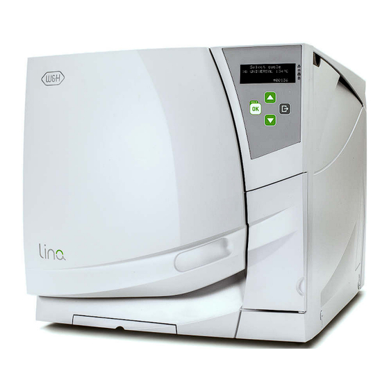
- Page 1 Posizione logo Instructions for use PRO13-003-17 PRO13-003-22 LINA ENG - Rev. 5...
- Page 2 Symbols Symbols displayed on the product and/or used in this manual: WARNING! ATTENTION! General explanations, Risk of injury To prevent damage occurring without risk to persons or objects Call service HOT SURFACES! HOT STEAM! Risk of burns Risk of burns Thermo washer Consult instruction for use Do not dispose of...
-
Page 3: Table Of Contents
Contents 1. Introduction ..................... 2. -
Page 4: Introduction
1. Introduction About this manual This manual contains the Instructions for Use of the W&H sterilizers LINA PRO13-003-17 and LINA PRO13-003-22, hereinafter referred to as LINA 17 and LINA 22. All drawings, images and texts contained in this manual are the property of the manufacturer. - Page 5 Introduction Qualifications of the users There are two types of users who may operate the sterilizer: The Advanced user is the head of the clinic/practice, who is legally responsible for the efficiency of the hygiene protocol in place as well as the sterilization process. He/she is also responsible for the USERS’ training and the correct operation and maintenance of the equipment.
-
Page 6: Unpacking
ON. The sterilizer must be removed from the box and transported by two people. Weight: LINA 17: 39 kg LINA 22: 40 kg Check the external conditions of the box and the sterilizer. In case of any damage, immediately contact your dealer or the shipping agent that has carried out the transport. - Page 7 Contents of the package Mains cable Tray (3 pieces total) Reversible rack Funnel USB pen drive (only if the USB option is installed) Wall spacer Tray holder Fast guide Declaration of conformity Documentation CD Warranty card Drain tube Works tests report Maintenance sheet...
-
Page 8: Safety Advice
3. Safety advice The user is responsible for the proper installation, the correct use and maintenance of the sterilizer in accordance with the • instructions listed in this manual. The sterilizer has not been designed for the sterilization of foodstuff or waste. •... -
Page 9: Installation And Start-Up
4. Installation and start-up Placement Place the sterilizer on a flat and level surface, far from sources of heat and from flammable materials. Do not place the sterilizer so that it is difficult to open the service door and operate on the controls in it. Do not place the sterilizer so that it is difficult to disconnect the power supply plug. - Page 10 Water tanks Filling the clean water tank Switch the sterilizer ON • Slide the tank cover to the right to access the clean water tank inlet. • Remove the cap from the tank inlet; • Insert the funnel and fill the water tank with app. 4 litres of distilled or demineralized water; •...
- Page 11 If inserted in a 90° degree rotated position, the rack holds 3 trays or 3 cassettes horizontally. Usable space in the chamber LINA 17: 195 x 195 x 297mm (WxHxD); equal to the volume of 11.5 litres. LINA 22: 195 x 195 x 390mm (WxHxD); equal to the volume of 15 litres.
- Page 12 Controls, commands, connections Front view Service door Water tank cover Tank filling cover - cap Bacteriological filter Mains switch Chamber door USB port (optional) Display Control panel Identification label Service door Door pin Door seal Used water drain (grey) Clean water drain (blue) Dust filter Sterilization chamber...
- Page 13 Connections Detail of the hydraulic connections (optional) Rear view Pressure safety valve cover Serial communication ports (male) Used water drain Water supply inlet Mains plug socket The water supply system must deliver demineralized water meeting the Mains cable guide requirements as listed in ANNEX 7. Do not add any chemical / additive to the water.
- Page 14 Controls and commands Switching ON the sterilizer Press the mains switch behind the service door to switch ON the sterilizer. The visual indicator on the mains switch turns green and the START screen (see next page) appears. “SLEEP” mode In “SLEEP” mode the display remains dark and the sterilizer chamber is no longer heated to save energy. If the sterilizer is not used for 12 hours, (the time interval can be changed, see Chapter 5 - Programming) it will automatically switch to “SLEEP”...
- Page 15 Display and icons First line Shows the title/purpose of the current page and invites you to take an action (e.g. select a cycle). Second line Warning, tank and printer icons Shows the active option/action (preceded by the cursor >). The cursor (>) preceding an icon means By pressing OK, the active option/action will be selected/executed.
- Page 16 Icons If one or more icons of the display are preceded by the cursor, please take the actions as outlined below: If an icon is preceded by the cursor, this means that an information message is present in the MESSAGES menu. Follow the instructions provided in Chapter 8 to read the relevant messages.
- Page 17 Control buttons The control panel shows four buttons: UP button Moves to the upper item in the list. Increases a number or a parameter. ECO-B option This label reminds you that, when starting BACK button a cycle, you can choose the ECO-B mode Aborts the action/function.
-
Page 18: Programming
5. Programming Initial setup Before using the sterilizer please program important parameters such as date, time, language, display backlight and contrast. This is done by means of the SETUP functions. Start screen and menu options When the sterilizer is switched ON, or when exiting from SLEEP mode, the default cycle program is displayed, preceded by the cursor. - Page 19 Table 1: list of the MENU options MENU SUB-MENU WHAT IT DOES Displays pending messages. Refer to Chapter 8 for a detailed list of messages. Select a previously recorded cycle. Press OK and then scroll the list of the recorded cycles with UP /DOWN.
- Page 20 UP/DOWN to increment/decrement the numbers, then press OK to print. Displays the device brand name; e.g. W&H. Displays the device model name; e.g. LINA. Displays the device type; e.g. PRO13-003-22. Displays the serial number of the sterilizer; e.g. 110009.
- Page 21 Table 2: Detail of the SETUP options MENU SUB-MENU WHAT IT DOES AND HOW TO SET IT Sets the language. The active language is displayed: press OK and scroll other available languages with UP or DOWN. When the new language is displayed press OK to confirm, or BACK to exit without saving.
- Page 22 Table 2: Detail of the SETUP options (continued) MENU SUB-MENU WHAT IT DOES AND HOW TO SET IT Sets the printer model See note (*) for instructions. Preheats the chamber ONLY if the chamber door is closed. Sets the preheating mode (**) See note (*) for instructions Chamber is never preheated.
- Page 23 How to log on as an advanced user Some programmable options of the LINA sterilizer can be changed only after logging in as an advanced user. This is to prevent accidental changes or unexpected operation of the sterilizer. Hiding a cycle program, making it inaccessible to users, is an example of option that can be accessed by advanced users only.
-
Page 24: Running A Sterilization Cycle
6. Running a sterilization cycle Place the sterilization load in the sterilizer chamber and close the door. See ANNEXES 2 and 3 on how to properly prepare and place the load. Switch the sterilizer ON by pressing the mains switch behind the service door. The start screen will show the default sterilization program, preceded by the cursor. - Page 25 Running a sterilization cycle After selecting the cycle: - the first line of the display shows the selected cycle. - the “START NOW” option appears: press OK to start the sterilization cycle immediately, otherwise see the next pages for the “delayed start” options. - the third and fourth lines show the maximum load weight limits for the selected cycle.
- Page 26 The available sterilization cycles In total there are three sterilization cycles available. All cycles are type B according to the European Standard EN13060, which means they are capable to sterilize all types of loads: full solid, porous, hollow A and B, plastics, rubber, etc.; unwrapped, bagged, single or double wrapped.
- Page 27 The available sterilization cycles CYCLE PROGRAM TABLE Model LINA 17 LINA 22 Max. load (instruments) 4 kg 5 kg 1.5 kg 1.8 kg Max. load (porous) Sterilization Holding Total cycle time Total cycle time CYCLE PROGRAM NAME temperature time (Drying time)
- Page 28 The sterilization cycle profile All available sterilization cycles feature the same basic pressure profile as shown in the graph below. The duration of the sterilization phase (or plateau time) and the sterilization temperatures differ between the various cycles. LEGEND Pressure Pre-heating (this is not considered a part of the cycle) Vacuum pulse (removal of air from...
- Page 29 The ECO-B option “ECO-B” is a cycle option designed to reduce the cycle duration and the overall energy consumption, providing a fast type B cycle for a limited load weight (0.5 kg of instruments only!). The “ECO-B” option is available for the cycles only.
- Page 30 The “Delayed start” options After selecting a cycle program, press UP or DOWN to scroll between the “start now”, “start at...” and “start in...” options. Select the desired option by pressing OK. The delayed start option is not available for all cycles. “Start at...”...
- Page 31 Customization of cycle parameters You can customize a cycle program by setting certain parameters according to your own sterilization protocol. The drying time can be changed only after acceding as an ADVANCED USER. The holding time may be changed by an authorized service technician only. Changing the drying time The duration of the drying time can be increased or decreased according to the characteristics of the load.
- Page 32 Cycle in progress Information displayed on the screen while a cycle is in progress First line changing between: - Name of the current cycle; - Progress bar (if enabled). Selectable options (preceded by the cursor to the left) Countdown By pressing UP or DOWN, certain options will be available Approximate residual time until cycle (e.g., changing the displayed information, aborting the completion.
- Page 33 Cycle in progress INFO screen and menu options While a cycle is in progress, you can view the main cycle parameters in real time. On the “cycle in progress” screen, press UP or DOWN until the INFO option appears. Other menu items are also available at this stage. Then confirm with OK.
- Page 34 Manual stop While a cycle is in progress, you can abort it manually at any time. Press UP or DOWN until the STOP option appears preceded by the cursor, then proceed as shown below: Confirm STOP (OK) Press DOWN until YES appears. Before the cycle abortion is confirmed, the abortion procedure can be interrupted at any time;...
- Page 35 Manual stop When the reset phase is over, press BACK One of the following messages appears: The message LOAD NOT STERILE means that the load is not sterile. Do not use items on patients! The message DRYING INTERRUPTED means that the load might be wet. Wet items are for immediate use only! Press OK to unlock the door as requested in the second line of the screen.
- Page 36 End of a sterilization cycle When a cycle is successfully finished, the CYCLE COMPLETED message appears on the screen and the “Unlock door” option is preceded by the cursor. At this stage you can press DOWN or UP until the INFO option appears; confirm INFO to view the cycle parameters (see previous pages).
-
Page 37: Maintenance
7. Maintenance Before carrying out any maintenance on the sterilizer, switch the unit OFF and remove the mains cable. Before accessing the chamber and the connected parts, be sure that the sterilizer is cold. Follow the instructions in this chapter when carrying out any maintenance on the sterilizer. Maintenance program The maintenance program is outlined in the table on the next page. - Page 38 Maintenance program MAINTENANCE PROGRAM TABLE Frequency (*) # of cycles (*) Operation Consumable Performed by Clean the door seal and the chamber face side Clean the chamber, trays and the rack Monthly Clean the chamber filter Clean the external sterilizer surfaces Clean the steam diffuser plate User See ANNEX 9...
- Page 39 Monthly or 50-cycle maintenance Cleaning the door seal and the chamber face side Clean the door seal and the outer edge of the chamber with a non-abrasive cloth moistened with water. If you use a detergent solution, be careful not to get in contact with the plastic body of the front cover.
- Page 40 Monthly or 50-cycle maintenance Cleaning the chamber filter Empty the sterilizer chamber by removing the trays and the rack. 1–2: Remove the filter cap at the back of the chamber (bottom/center) by turning it counter-clockwise. 3: Remove the cartridge filter and rinse it with tap water. 4–5–6: Insert the filter in the cap, attach the filter cap and lock it by turning clockwise.
- Page 41 3 month or 400-cycle maintenance Replacing the bacteriological filter Open the service door. Unscrew the bacteriological filter by hand (counter-clockwise). Screw on the new bacteriological filter (clockwise) and tighten it snug. Remember to reset the counter after replacement (see following pages). Replacing the dust filter Pull out the dust filter from underneath the sterilizer.
- Page 42 6 month or 800-cycle maintenance Cleaning the water tanks Switch OFF the sterilizer and disconnect the mains cable. Completely drain both tanks. Leave the drain tube attached to one of the drain quick connectors. Turn the 5 screws of the tank cover a ¼ with the use of a screwdriver (a coin works as well) and lift the cover to gain access to the tanks.
- Page 43 1 year or 800-cycle maintenance Replacing the door seal Fully open the chamber door. Pull out the used door seal by hand (easy if seal and fingers are dry). Carefully clean the seal seat and the chamber face side with a cotton swab. Moisten the new seal with water.
- Page 44 4000 cycle/5 years general check and service Regular service is imperative to ensure continuous and effective operation of the sterilizer. It is recommended to carry out a general service every 4000 cycles or five years by an authorized service technician. The service includes replacement of consumables and other important internal components, a check of the entire unit with special care for the safety systems, and cleaning of areas and components that cannot be accessed by the user.
- Page 45 Resetting the maintenance counters Use the UP, DOWN and OK buttons to browse the menu, choosing the following options in sequence: MENU – DEVICE INFO – SERVICE COUNTERS. Scroll to the concerned consumable by pressing UP or DOWN. The consumable status (number of cycles executed and maximum lifespan of the consumable) is displayed in the third and fourth line of the display.
-
Page 46: Troubleshooting, Alarms And Messages
8. Troubleshooting, alarms and messages If the cursor appears to the left of one or more icons, there is related information pending. All messages can be viewed by means of the MESSAGES sub-menu. Use the UP, DOWN and OK buttons to browse the menu, choosing the following options in sequence: MENU - MESSAGES If there is more than one message pending, you can scroll within messages with UP or DOWN. - Page 47 Messages ICON MESSAGE DESCRIPTION/ACTION REQUIRED The chamber door is locked; no action required. The water level inside the clean water tank is below the minimum. Fill the clean water tank. The water level inside the used water tank is at maximum level. Drain used water tank. Check the external sterilizer water supply.
- Page 48 Alarm stop In case certain important sterilization parameters are not met, the sterilizer will generate an alarm code and abort the cycle automatically. The sterilizer enters into a reset phase; a wait message and an alarm code are displayed on the screen. At this stage select and confirm “Info”...
- Page 49 Alarms Alarm code DESCRIPTION ACTION E010 Power failure during a cycle Load cannot be considered sterile. Repeat the cycle. E02x Internal voltage error Switch the sterilizer OFF and ON. If the problem persists call service. Switch the sterilizer OFF and ON. If the problem persists call service. E041 Cycle counter lost NOTE: Initiating a sterilization cycle is still possible.
- Page 50 Alarms Alarm code DESCRIPTION ACTION After the process phase the pressure took too long to drop to the atmospheric pressure. If the problem Pressure drop timeout E182 persists call service. E184 Overtemperature detecded If the problem persists call service. E215 Fan blocked or faulty electronic control Call service.
- Page 51 Resetting the thermal overload A safety thermostat is fitted on the sterilizer to prevent overheating of the electric heater. If the safety thermostat operates because of too high temperatures, the alarm E240 or a timeout alarm is generated. If this happens, proceed as follows: - Switch the sterilizer OFF and remove the mains cable.
- Page 52 Troubleshooting PROBLEM POSSIBLE CAUSE SOLUTIONS The main switch or network circuit breaker is OFF Activate the main switch or network circuit breaker (ON). The sterilizer remains switched No voltage at the socket Check the electric circuit. OFF. The mains cable is not properly connected Attach the cord set properly.
- Page 53 Troubleshooting PROBLEM POSSIBLE CAUSE SOLUTIONS Door seal not properly placed; seal sticking out Ensure that the door seal is evenly inserted on the entire circumference. When starting a cycle, the chamber door locks but re-opens OK button was pressed twice to launch the cycle Try again by pressing OK only once.
-
Page 54: Recycling And Disposal
9. Recycling and disposal LINA sterilizers are mainly built from fiber-reinforced polymers, metals and electronic components. In case of disposal: - separate the various components according to the materials they are made of; - drop the sterilizer with a company that specializes on the recycling of related products;... -
Page 55: Technical Data
22 l/Ø 250 mm x D 440 mm (LINA 22) Usable space (for all cycles) 11.5 l/W195 mm x H 195 mm x D 297 mm (LINA 17) 15 l/W 195 mm x H 195 mm x D 390 mm (LINA 22) Bacteriologicalfilter: 0.3 µm... -
Page 56: Maintenance Of Dental Handpieces
ANNEX 2. Maintenance of dental handpieces External disinfection This procedure reduces the risk of infection during cleaning and maintenance of the instrument. Wear protective gloves during disinfection. Refer to the instructions of the instrument manufacturer. Avoid using abrasive disinfectants (pH-value 2.5 – 9; no chlorine based disinfectants). We recommend the use of disinfectant wipes rather than spray disinfection. -
Page 57: Sterilization Load Preparation
ANNEX 3. Sterilization load preparation Cleaning the instruments Clean all instruments thoroughly prior to sterilization. If possible, clean instruments immediately after use; always follow the instrument manufacturer ‘s instructions. Remove all traces of disinfectants and detergents. Rinse and dry carefully all instruments. Lubricate dental handpieces after cleaning and prior to sterilization in accordance with the manufacturer’s instructions. - Page 58 Loading the chamber Tubes Rinse, drain and dry tubes after washing. Place tubes on a tray allowing the ends to remain open. Do not bend tubes. Partial loads If the chamber is just partially loaded, place the load in such a way that the space in-between the trays is maximized (see example with three trays on the left).
-
Page 59: Bowie & Dick Test
ANNEX 4. Bowie and Dick test Description The Bowie & Dick (B&D) test device is used to validate the sterilizer performance for textile load sterilization. It is made of several sheets of paper wrapped in a small packet in the middle of which there is a chemical heat-sensitive indicator sheet. How to carry out the test The test must be performed in an empty chamber (EN13060) without load but with the standard chamber accessories (chamber rack and trays) mounted. -
Page 60: Helix Test
ANNEX 5. Helix test Description The Helix test device is used to validate the sterilizer performance for hollow items. It consists of a 1,500 mm long tube that is open on one side and closed with a capsule on the other side. A chemical indicator strip is placed inside of the capsule. How to carry out the test The test must be performed in an empty chamber (EN13060) without load but with the standard chamber accessories (chamber rack and trays) mounted. -
Page 61: Vacuum Test
ANNEX 6. Vacuum test Description The vacuum test is designed to validate the sterilizer performance in terms of: • Efficiency of the vacuum pump; • Tightness of the pneumatic circuit. It consists of a vacuum phase, followed by a stabilization period of 5 minutes and a testing period of 10 minutes. During the 10-minute testing period the internal pressure is monitored. -
Page 62: Water Quality
ANNEX 7. Water quality LINA sterilizers use distilled or demineralized water to generate steam for the sterilization process. The table below lists the maximum content of minerals and the specifications for the water used for steam sterilization (see EN13060 ANNEX C). -
Page 63: Example Of A Cycle Data Report
ANNEX 8. Example of cycle data report Sterilizer brand Sterilizer model and serial number Surgery – practice – doctor name Cycle name Cycle counter Programmed sterilization temperature Programmed sterilization time Programmed drying time Cycle start date and time Headers for the table below Cycle start Pre-heating phase Pressure and vacuum pulses... -
Page 64: Accessories And Spare Parts
ANNEX 9. Accessories and spare parts Aluminium tray Printer model S'Print LINA17: part n. F523204x part n. 19721108 LINA 22: part n. F523205x Label printer LisaSafe Tray holder part n. 19721101 (with bar code reader) part n. F523001x part n. 19721102 (without bar code reader) Funnel part n. - Page 65 Accessories Cycle report printer (S'Print) - part n. 19721108 S'Print is a compact, reliable and easy-to-use printer that can be connected directly to the serial port located in the rear of the sterilizer. S'Print can be easily managed from the sterilizer control panel (See Chapter 5 - Programming) in order to: - Print cycle data reports (see ANNEX 8 “Example of a cycle data report”) at the end of each cycle either in automatic or manual print mode;...
- Page 66 Accessories USB port + additional serial port kit - part n. X051124x Mount this kit if you want to connect a USB pen drive to save the cycle reports, or an additional serial device (e.g. a label printer). The kit must be installed by an authorized service technician, or by the factory upon specific order request.
- Page 67 Accessory connection schemes Data communication Water treatment, supply and drain LisaSafe drive External water Kit USB (*) filtration system (*) S’Print Water feed system Osmo (*) Rear serial connections (with USB kit) (*) The water filtration system must be fitted with a backflow preventing device complying to IEC 61770 and to national and local regulations.
- Page 68 Accessories and spare parts Standard chamber rack for 3 cassettes (*) 190x43x300/375 * LINA 17: part n. F523008x 190x43x300/375 * LINA 22: part n. F523009x 190x43x300/375 * Standard chamber rack for 3 USA size cassettes (*) 205x35x300/375 * LINA 17: part n. F523020x 210x35x300/375 * LINA 22: part n.
- Page 69 Consumables Bacteriological filter - part n. W322400x Replace every 400 cycles Door seal - part n. F460504x Replace every 800 cycles Dust filter - part n. F364502x Replace every 400 cycles 400-800 cycle consumable kit - part n. X050315x This kit consists in a stock of consumables suitable to run 800 cycles. It includes: - 1 door seal;...
-
Page 70: 10Helix Test Documentation Form
ANNEX 10. Helix test documentation form Use this page to create a logbook tracing the effectiveness of the sterilization cycle during the whole lifespan of your sterilizer. Date Cycle N. Operator Released Signature Chemical indicator YES NO YES NO YES NO YES NO YES NO YES NO... - Page 71 YES NO YES NO YES NO YES NO YES NO YES NO YES NO YES NO YES NO YES NO YES NO YES NO YES NO YES NO...
-
Page 72: H Installation Check-List
APPENDIX 11. W&H Installation check-list 1 Was the head of the clinic/practice present during all the in-service? 2. Is the packing of the sterilizer undamaged? 3 When unpacked, is the sterilizer undamaged? 4 Are all the contents of the package available (sterilizer ship-with)? 5 Are all the ordered accessories available with the sterilizer? 6 Have you removed all the protection covers from the sterilizer and from all the ship-with? 7 Were all sections of the instruction for use of the sterilizer covered and explained during the in-service? - Page 73 APPENDIX 11. W&H Installation check-list 23 Have you executed a Vacuum test? 24 Have you executed a B Universal 134°C cycle program with the tray rack and trays inserted? 25 Have you explained to the head of the clinic/practice the correct load type for each available sterilization program? 26 Have you showed to the head of the clinic/practice how to prepare and place the load in the sterilizer chamber? 27 Have you explained to the head of the clinic/practice to use only original parts and accessories on the sterilizer? 28 Have you showed and explained to the head of the clinic/practice the safety advise section?
- Page 74 Notes...
- Page 75 Authorized W&H service partners Find your nearest W&H service partner at http://wh.com Simply go to the menu option »Service« for full details. Alternatively please contact: W&H UK LIMITED, 6 Stroud Wood Business Centre, Park Street, St.Albans, Herts AL2 2NJ t +44 1727 874990 f +44 1727 874628 technical.uk@wh.com A-DEC AUSTRALIA CO.INC., Unit 8, 5-9 Ricketty Street, Mascot NSW 2020,...
- Page 76 Manufacturer LINA PRO13-003 ENG - Rev. 5 W&H Sterilization S.r.l. Italy, I-24060 Brusaporto (Bg), via Bolgara, 2 t +39/035/66 63 000 f +39/035/50 96 988 Subject to alterations wh.com 10.01.2019...
Need help?
Do you have a question about the PRO13-003-17 and is the answer not in the manual?
Questions and answers