Table of Contents
Advertisement
Quick Links
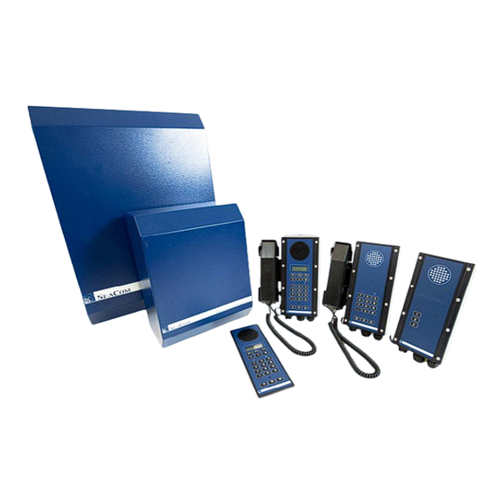
SeaCom System Manual
The manual for the SeaCom 2100 maritime intercom system
• Covers SeaCom 2100 telephone system
• Covers SC211, SC220, SC411 and SC421 stations
• Covers the Windows based configuration tool
• Valid for the SeaCom 19'' systems as well
Søren Frichs Vej 38
DK-8230 Aabyhøj Denmark
www.seacom.dk
telephone: +45 86 296 297
Advertisement
Table of Contents

Related Manuals for SeaCom SC211


Summary of Contents for SeaCom SC211
- Page 1 SeaCom System Manual The manual for the SeaCom 2100 maritime intercom system • Covers SeaCom 2100 telephone system • Covers SC211, SC220, SC411 and SC421 stations • Covers the Windows based configuration tool • Valid for the SeaCom 19'' systems as well Søren Frichs Vej 38...
- Page 2 SeaCom System Manual Page 4 of 139 SeaCom 10-600-0010_0405 TMN100510CJ01_0405...
- Page 3 SeaCom System Manual Page 5 of 139 SeaCom 10-600-0010_0405 TMN100510CJ01_0405...
- Page 4 SeaCom System Manual Page 6 of 139 SeaCom 10-600-0010_0405 TMN100510CJ01_0405...
- Page 5 SeaCom System Manual Page 7 of 139 SeaCom 10-600-0010_0405 TMN100510CJ01_0405...
-
Page 6: Table Of Contents
TATIONS 4.2.2 411 ........21 6.7.2.1 SeaCom 211 the talk-back stations31 4.2.3 211 ........22 6.7.2.2 SeaCom 220 industrial telephone . 31 4.2.4 421 ........22 6.7.2.3 SeaCom 421 and SeaCom 411..31 4.2.5 220 ........22 6.7.3 ........31 RUNK LINES .. - Page 7 ........54 . 37 IGITAL INPUT ATTERIES OF ANALOGUE TELEPHONES 10.6.7 ......54 ONE RELAY DRIVE 10.6.8 .......... 54 UMPERS SEACOM 2100 ............ 38 10.6.9 ......... 55 OARD LAYOUT 10.7 CTU2 ..........56 10.7.1 ....... 56 ECHNICAL DATA ........38 PECIFICATION 10.7.2...
- Page 8 SeaCom System Manual Page 10 of 139 STATIONS ............64 11.4.7 ..........85 11.4.7.1 F1 to F3 ........85 11.4.7.2 Up down keys ......85 11.1 ....64 ECHANICS AND MOUNTING 11.4.7.3 M key ........... 85 11.1.1 ......... 64 HE KEYBOARD 11.4.7.4...
- Page 9 SeaCom System Manual Page 11 of 139 11.4.13.2.31 Voice hook off ....... 91 12.4.2 ...... 106 HE DIRECTORY GRID 11.4.14 ..... 92 12.4.3 ......... 107 ECHANICAL OUTLINE OP UP MENU 11.4.15 ........93 12.4.3.1 Properties menu ......107 LAYOUT 11.4.16 ........
- Page 10 SeaCom System Manual Page 12 of 139 12.5.6.2.3 Audio enable ......114 12.5.20 ‘D ’ ..122 O NOT DISTURB SYSTEM CALL 12.5.6.2.4 Connection time limit ....114 12.5.20.1 Call number / Description ..122 12.5.6.2.5 Routing list ......115 12.5.20.2...
- Page 11 SeaCom System Manual Page 13 of 139 13.7.2.3 Called number ......129 13.7.3.4 Base charge and Charge pr. Minute132 13.7.2.4 Duration ........130 13.7.4 ....132 HORT NUMBER EDITOR 13.7.2.5 Charge ........130 13.7.2.6 Group ......... 130 CP AND ITS APPLICATIONS ......133 13.7.2.7...
-
Page 12: Introduction
SeaCom System Manual Page 14 of 139 1. Introduction Thank You for choosing SeaCom as Your supplier of wired on board communication. This manual will introduce You to our maritime communication system, and take You through all parts of the process from evaluating the... -
Page 13: Important Safety Notes
NEVER leave the exchange without • the cover put back on. The SeaCom 2100 is enclosed by a • heavy steel box. Handle these with care and mount the properly fastened, so they do not drop of their brackets. -
Page 14: System Description
Users can set up a fixed conference, or the 3.1 Purpose of the system conference can be dynamic created, left and The purpose of the SeaCom 2100 maritime joined. communication system is to give the seamen easy and reliable on board communication 3.2.5 PA functions... -
Page 15: Ain System Components
SeaCom System Manual Page 17 of 139 3.3 Main system components 3.3.2 Exchange circuit boards A SeaCom installation consist of the following In order to build exchanges that suits the main components: customers needs, a range of circuit boards are... -
Page 16: Ommunication Stations
SeaCom System Manual Page 18 of 139 FIO4 A circuit board adding 2 or 4 trunk lines Power distribution. Used for distributing the (satellite) channels to the system. 24V DC power to stations. This board also holds audio I/O and a lot of relay functions. -
Page 17: Elephones
Connect handset and headset. Used in engine spaces, and on deck. 3.3.6 Telephones For dry and heated spaces on board SeaCom recommend our digital telephone TX325 or the direct-in/PA enabled SC325 telephone. They are digital telephones displaying date/time, caller number and caller name. -
Page 18: Typical Installation Example
SeaCom System Manual Page 20 of 139 3.4 Typical installation example The figure shows an example of how the SeaCom communication system can be architectured. SeaCom 10-600-0010_0405 TMN100510CJ01_0405... -
Page 19: Designing A System
The table shall be used as a guide only to choose among the numerous possibilities 4.1.2 Environment given by the SeaCom maritime communication system. On each location, the expected noise level must be known, and the location must be The below describes which type of station to be used in each type of environment. -
Page 20: Ea Om 211
These are the stations SeaCom 411, SeaCom 211and 4.2.5 SeaCom 220 SeaCom 421. If the number is 4 or less, the auxillary output of the power input module This is a plain analogue telephone with (PIM) found internal to the exchange systems optional handset or headset. -
Page 21: Assembling The Exchange
SeaCom System Manual Page 23 of 139 4.4 Assembling the exchange The exchanges must be assembled according to the customer requirements. This paragraph takes you through the assembly process. 4.4.1 Card guides In order to insert circuit boards into the board magazine, plastic card guides must be used. -
Page 22: Fusing
4.5.4 Power consumption - stations Except for the analogue telephones and the SeaCom 220, all the communication stations At the lowest right corner of the cable also require 24V DC power. The power termination area, is the PIM (power input... -
Page 23: First Time Power Up
SeaCom System Manual Page 25 of 139 4.7 First time power up two power inputs to make it turn off. two power inputs to make it turn off. If only single power is used, then link the two If only single power is used, then link the two... -
Page 24: Installation
When 24V DC power is take to the stations, these shall be done in the same cable as the telephone line. This means that a 2x2wire twisted pair shall laways be used for SC211, SC411 and SC421. 5.3 Wiring diagram... -
Page 25: Mounting The Stations
Refer to chapter 11.3. 5.5.1 Bulkhead The communication stations SeaCom 211, SeaCom 421 and the SeaCom 220 are all boxed and mounted on a bulkhead. It is delivered with an isolating gasket and isolating washers, so that it is possible to... -
Page 26: Fuses
SeaCom 421 and SeaCom 411 but it is If a multi core cable is used out of the NOT recommended. exchange, conducting several extension lines to a junction box where it is split into a number 5.7 Shielding and protective earth... - Page 27 SeaCom System Manual Page 29 of 139 This figure shows schematically the way the shields should be connected. Note that there is only one point of connection to ship’s hull / PE. SeaCom 10-600-0010_0405 TMN100510CJ01_0405...
-
Page 28: Commissioning
If an extension line is connected to a SeaCom 411 station, the line must be set up to be of such type for example the direct in calls to work properly. -
Page 29: Access Privileges
6.7.2.1 SeaCom 211 the talk-back stations calls via a satellite service, whereas a crew telephone will only be able to receive calls on The SeaCom 211 station have gains to be set the same service. for adjusting gains of microphones and This is done using service groups or access speakers. -
Page 30: Access Privileges
It is the responsibility of the company commissioning the system to create an end user manual. This manual is to be used by the crew members using the SeaCom system. Take chapter 7 as a starting point for this manual. -
Page 31: Operation
Talk back call free mode and conversations or listening is (3 short ringing with 5s pause) effective. Direct in to the SeaCom 211station is to be ___ ___ ___ ___ ___ ___ considered a single station PA call, as it is... -
Page 32: Setting System Time
Dial: to access the CDM service 7.7 Setting system time Dial: Two digits account number The system time of the SeaCom system can Dial: PPPP Four digits pin code be adjusted by a calling the below numbers: Dial: 004586296297# #120 + 8 digits date (YYYYMMDD) Wait for answer and speak. -
Page 33: Call Pickup
During a conference call, participants can leave or join the conference. If the call is made from a SeaCom 411 to one An extension that like to join a conference or more SeaCom 211’s, the speech direction shall call the #07 call number. -
Page 34: Day - Mode Night - Mode
SeaCom System Manual Page 36 of 139 7.20 Day-mode night-mode Call #031 to activate night-mode, and call #030 to activate day-mode. This is a highly flexible functions typically used to set where incoming calls are directed during day time and during night time. -
Page 35: Maintenance
SeaCom System Manual Page 37 of 139 8.2 Batteries of analogue telephones 8. Maintenance If the TX-325 telephones are used, the hands- When the system is properly installed there is free function and the display function depends no daily maintenance, but some components on batteries. -
Page 36: Seacom 2100
SeaCom System Manual Page 38 of 139 9.2 Exploded view 9. SeaCom 2100 Below figure shows the interior. The SeaCom 2100 is our largest boxed and type approved maritime communication system 9.1 Specification 8 to 256 analogue extensions 2 to 10 2 wire trunk lines... -
Page 37: Mechanical Outline
SeaCom System Manual Page 39 of 139 9.3 Mechanical outline SeaCom 10-600-0010_0405 TMN100510CJ01_0405... -
Page 38: The System Inside
SeaCom System Manual Page 40 of 139 9.4 The system inside This chapter describes common parts that are inside the systems. 9.4.1 Board magazine The top of the systems holds the board magazine, carrying the circuit boards of 100x220mm wired in a bus system by the backplane. -
Page 39: Circuit Boards
SeaCom System Manual Page 41 of 139 10. Circuit boards. Circuit boards. This chapter holds detailed technical This chapter holds detailed technical information about all circuit boards used in the information about all circuit boards used in the exchange systems. -
Page 40: Fan Drive
SeaCom System Manual Page 42 of 139 10.1.5 Fan drive An open collector output is used to drive a fan relay located on the PIM module. The fan relay is activated based on temperature measurements. 10.1.6 Input power supervision If the source supply voltage is below 18V the power supply will switch off and stay as such until the input voltage exceeds 20V. -
Page 41: Layout
SeaCom System Manual Page 43 of 139 10.1.8 Layout SeaCom 10-600-0010_0405 TMN100510CJ01_0405... -
Page 42: Cp2 Central Processor
SeaCom System Manual Page 44 of 139 10.2 CP2 central processor The purpose of the CP2 board is to execute the CP software which is the very brain of the exchange system, and to hold the 10.2.2 Serial port configuration file which stores call numbers, privilege settings etc. -
Page 43: Advantec 10.2.4 Indicators
SeaCom System Manual Page 45 of 139 10.2.4 Indicators The CP2 board has 5 indicators. Indicator Disk activity Green - Flashing when disk access is going on Green and red - for receive and red for transmit Flashing when communicating... -
Page 44: Fio2 Master And Slave
SeaCom System Manual Page 46 of 139 10.3 FIO2 master and slave 10.3.2 Technical data 2 channels • trunk and audio in/out trunk and audio in/out galvanic isolated (1.0kV) • 600 ohm trunk line • 600 ohm audio in/out ohm audio in/out •... -
Page 45: Line Activity Indicators
SeaCom System Manual Page 47 of 139 10.3.4 Line activity indicators ndicators 10.3.6 Trunk line circuits Trunk line circuits The FIO2 board has 4 line activity indicators The FIO2 board has 4 line activity indicators, The 2 wire analogue trunk line is used for... -
Page 46: Layout
SeaCom System Manual Page 48 of 139 10.3.8 Layout SeaCom 10-600-0010_0405 TMN100510CJ01_0405... -
Page 47: Aext8
SeaCom System Manual Page 49 of 139 10.4 AEXT8 10.4.2 Front connector connector Extensions are connected Extensions are connected via the 16 pin front connector. All connections are in pairs of two connector. All connections are in pairs of two... -
Page 48: Layout
SeaCom System Manual Page 50 of 139 10.4.4 Layout SeaCom 10-600-0010_0405 TMN100510CJ01_0405... -
Page 49: The Aext16
The AEXT16 is the telephone line card of the One, and only one, board of a SeaCom system. The AEXT that comes with the system must behave like a master board. The... -
Page 50: Board Layout
SeaCom System Manual Page 52 of 139 10.5.3 Board layout The board layout is shown below: SeaCom 10-600-0010_0405 TMN100510CJ01_0405... -
Page 51: The Fio4
SeaCom System Manual Page 53 of 139 10.6 The FIO4 10.6.2 FIO4 Connectors The picture below shows the Flexible IO card: The 3 tables below shows the pin out of the 3 lines connectors. Trunks and audio I/O: Pin 1,2... -
Page 52: Trunk Lines
SeaCom System Manual Page 54 of 139 10.6.3 Trunk lines 10.6.8 Jumpers The FIO4 implements good old 2 wire trunk This paragraph is of importance only if You lines with the following main specifications: plan to use the FIO4 as system master card. -
Page 53: Board Layout
SeaCom System Manual Page 55 of 139 10.6.9 Board layout The board layout is shown below: SeaCom 10-600-0010_0405 TMN100510CJ01_0405... -
Page 54: Ctu2
16 extensions and 2 trunk lines 16 extensions and 2 trunk lines • 10.7.2 Using the CTU2 The SeaCom system makes s use of prefabricated 16 wire ribbon cables between prefabricated 16 wire ribbon cables between boards of the board magazine and the boards of the board magazine and the termination units. -
Page 55: Ctu24
• 16 extensions and 2 trunk lines • 10.8.2 Using the CTU24 The SeaCom system makes use of prefabricated 16 wire ribbon cables between boards of the board magazine and the termination units. These cables comes in a selection of lengths to suit the needs. -
Page 56: Pdu
SeaCom System Manual Page 58 of 139 10.9.2 Using the PDU 10.9 PDU T24V DC is applied to the green power input T24V DC is applied to the green power input connector. This power is distributed via the 4 connector. This power is distributed via the 4... -
Page 57: Layout
SeaCom System Manual Page 59 of 139 10.9.4 Layout SeaCom 10-600-0010_0405 TMN100510CJ01_0405... -
Page 58: Pim
SeaCom System Manual Page 60 of 139 10.10 PIM 10.10.2 J1 power input J1 power input The purpose of the PIM (power input The purpose of the PIM (power input module) The use of J1 is is to make a common power entry point for... -
Page 59: Indicators
SeaCom System Manual Page 61 of 139 10.10.5 Indicators 10.10.8 AC connectors The PIM has 3 indicators: As an option, the PIM module has an AC in (J2) and an AC out (J4) connector with a fuse in between (F5). These are used if an AC/DC... -
Page 60: Backplane
24V DC main power 4V DC main power and - This backplane is used for the This backplane is used for the SeaCom 2100. Open collector fan drive Max 40V, Open collector fan drive Max 40V, 10.11.1 Technical data 100mA Dual 24V DC power input •... -
Page 61: Layout
SeaCom System Manual Page 63 of 139 10.11.4 Layout 10.11.5 SeaCom 10-600-0010_0405 TMN100510CJ01_0405... -
Page 62: Tmn100510Cj01
The SeaCom 211, SeaCom 220 SeaCom 220, SeaCom 421 cable part to which the ship cables are which the ship cables are and the SeaCom 411 are communication re communications. connected. These communication stations share the These communication stations share the... -
Page 63: M Ounting Brackets
SeaCom System Manual Page 65 of 139 11.1.4 Mounting brackets On the backside of the box two stainless steel x two stainless steel mounting brackets are found. mounting brackets are found. Refer to chapter 5.7 discussing shielding. discussing shielding. The PE terminal should NOT be connected to... -
Page 64: T He Handset
SeaCom System Manual Page 66 of 139 11.1.7 The handset aluminum box. The range of stations can be connected to our The range of stations can be connected to our water resistant and salt mist tolerant handset. water resistant and salt mist tolerant handset. - Page 65 This door gives additional mechanical robustness while still being acoustical open, robustness while still being acoustical open, so the SeaCom 421 can be used in hands can be used in hands- free. With the door mounted, the statio free. With the door mounted, the stations can...
-
Page 66: Mounting The Door
SeaCom System Manual Page 68 of 139 The door can also be used to give additional The door can also be used to give additional Then mount the stud in both top and bottom of Then mount the stud in both top and bottom of... -
Page 67: F Eatures Overview
SeaCom System Manual Page 69 of 139 11.1.10 Features overview The table below shows the features of the stations: Feature Handset connection Headset connection Exposed door option Call relay External speaker External microphone Display Hands free operation Keys Speed dial... -
Page 68: H Andset Mechanical Outline
SeaCom System Manual Page 70 of 139 11.1.11 Handset mechanical outline 11.1.12 Cross rail drawing SeaCom 10-600-0010_0405 TMN100510CJ01_0405... -
Page 69: D Escription
Page 71 of 139 11.2 SeaCom 211 11.2.2 Specification The picture below shows the The picture below shows the SeaCom 211 in The SeaCom 211 has the below features: has the below features: a full equipped configuration with headset and... -
Page 70: E Lectrical Connections
SeaCom System Manual Page 72 of 139 11.2.4 Electrical connections 11.2.5 Jumper field The station is connected using 2 12 pole The station is connected using 2 12 pole J3 is a jumper field used to selec is a jumper field used to select or program screw terminal connectors: some functionality. -
Page 71: O Perating
11.2.7.6 Command group (talk-back) answered, the answer will be heard in the loudhailer and headset. The SeaCom 211 is to be used in a command If the call is not answered, press the button group conference, also called a talk-back call. -
Page 72: M Echanical Outline
SeaCom System Manual Page 74 of 139 11.2.8 Mechanical outline SeaCom 10-600-0010_0405 TMN100510CJ01_0405... -
Page 73: Pcb Layout
SeaCom System Manual Page 75 of 139 11.2.9 PCB layout SeaCom 10-600-0010_0405 TMN100510CJ01_0405... -
Page 74: S Chematic
SeaCom System Manual Page 76 of 139 11.2.10 Schematic SeaCom 10-600-0010_0405 TMN100510CJ01_0405... -
Page 75: D Escription
SeaCom 220 11.3.2 Specification 11.3 The picture below shows the The picture below shows the SeaCom 220 The SeaCom 220 has the below features: has the below features: water tight, salt mist resistant t ater tight, salt mist resistant telephone in a... -
Page 76: I Nside
SeaCom System Manual Page 78 of 139 11.3.4 Inside 11.3.6 Programming The telephone has a set of configuration The telephone has a set of configuration parameters which are set up by the parameters which are set up by the installer by use of the keyboard. -
Page 77: O Perating
The full duplex mode is indicated by the green indicator steady on. This paragraph describes how to use the This paragraph describes how to use the SeaCom 220 station as seen from the end station as seen from the end users view. 11.3.7.4 Receiving calls... -
Page 78: M Echanical Outline
SeaCom System Manual Page 80 of 139 11.3.8 Mechanical outline SeaCom 10-600-0010_0405 TMN100510CJ01_0405... -
Page 79: Pcb Layout
SeaCom System Manual Page 81 of 139 11.3.9 PCB layout SeaCom 10-600-0010_0405 TMN100510CJ01_0405... -
Page 80: S Chematic
SeaCom System Manual Page 82 of 139 11.3.10 Schematic SeaCom 10-600-0010_0405 TMN100510CJ01_0405... -
Page 81: D Escription
Although the versations. Although the The SeaCom 411 and the SeaCom 421 SeaCom 421 are SeaCom 411 has an 8W build in high quality has an 8W build in high quality our topmost stations will all features. will all features. -
Page 82: O N The Front
MFC panel. The MFC panel is a computer which through the serial is a computer which through the serial interface can control the interface can control the SeaCom 411 and the SeaCom 421 station station Transmit ++... -
Page 83: K Eys
This condition exist when a semi duplex conference call is made The SeaCom 411 is differing from the other from a SeaCom 411 to one or more SeaCom stations by beeing a flush mount station. This 211 stations. - Page 84 SeaCom System Manual Page 86 of 139 accomplished as the SeaCom 411 SeaCom 411 has an isolating gasket at the rim of the aluminum at the rim of the aluminum frame And it is supplied with 6 isolation washers And it is supplied with 6 isolation washers (“hats”), which are used when mounting the...
-
Page 85: O Perating
Calls marked with ‘!’ in incoming call list, are 11.4.12.1 Modes of conversation missed calls. The SeaCom 411 and the SeaCom 421 can If the phone is indicating a lost call when idle, be in conversation in the following modes: ’▼’... -
Page 86: Pa Call And Pa Volume
When making a handset call, the MIC button is used in the same way to make the call a PTT call or a full duplex handset call. The SeaCom 411 can be used as talk-back conference master using the handset in PT T mode. -
Page 87: T He Menu System
Page 89 of 139 11.4.13 The menu system 11.4.13.2.1 Speaker volume Used to preset the speaker volume. The SeaCom 411 and the SeaCom 421 has a comprehensive menu system which is 11.4.13.2.2 Backlight described in this chapter. Adjust level of backlight. -
Page 88: Direct In
FSK. the PTT button on the SeaCom 411 itself. Data format MUST be text string like : If hands free communication is wanted, a YY/MM/DD HH:MM. -
Page 89: Headset Vox
SeaCom System Manual Page 91 of 139 11.4.13.2.22 Headset VOX 11.4.13.2.27 Relay mode This parameter, when set to enable, activates This menu item is controlling the behavior of the headset VOX function. This is a voice the relay: controlled PTT function on the headset. -
Page 90: Tmn100510Cj01
SeaCom System Manual Page 92 of 139 11.4.14 Mechanical outline SeaCom 10-600-0010_0405 TMN100510CJ01_0405... - Page 91 SeaCom System Manual Page 93 of 139 11.4.15 PCB layout SeaCom 10-600-0010_0405 TMN100510CJ01_0405...
- Page 92 SeaCom System Manual Page 94 of 139 11.4.16 Schematic SeaCom 10-600-0010_0405 TMN100510CJ01_0405...
- Page 93 SeaCom System Manual Page 95 of 139 SeaCom 10-600-0010_0405 TMN100510CJ01_0405...
- Page 94 SeaCom System Manual Page 96 of 139 SeaCom 10-600-0010_0405 TMN100510CJ01_0405...
-
Page 95: System Programming
USB key disk \SeaCom2000 folder and In order to get USB access to the open the mx.mcf file. configuration file, a SeaCom USB key must be used. Insert the key into the lowest USB port of the powered on and operating SeaCom system. - Page 96 Take the USB key and insert into the USB port Start by giving the network port of the labtop a of the SeaCom system. The system will now fixed IP address. read the mx.mnw file, bring it into use, and delete it from the USB key.
- Page 97 SeaCom2000 disk using the explorer, or you can connect using the WINvnc (ref 14.3). 12.1.3.3 Mapping the system disk Next task is to map the disk of the SeaCom system, so we can see and use the contents of the disk.
- Page 98 SeaCom System Manual Page 100 of 139 When the contents of the system disk is When the file open dialog box appears, displayed, right click on the SeaCom2000 navigate to the S:\SeaCom2000 folder and folder and select the menu Map Network Drive open the mx.mcf file found there.
- Page 99 SeaCom System Manual Page 101 of 139 12.2 General concepts To open the editor used to include a call number to a service group, the below buttons This chapter contains descriptions of basic are available for all call numbers: set-up concepts.
- Page 100 The user dials *, which is the default call number of this type system call. When the processor of SeaCom encounters that the dialed number is a priority call, then it presents the caller of a new dial tone, and makes a priority call to the dialed number.
- Page 101 "_new" file. This is a signal file used by the This menu opens the physical editor to be SeaCom 3000 system only. used with SeaCom 2100 and 19'' systems. Refer to own manual for SeaCom 3000. 12.3.1.5 Exit Used to close the application. This will automatically save the file.
- Page 102 Page 104 of 139 12.3.4 Classic editor This board contains 8 individuals, which can This menu is only valid for the SeaCom 3000 be selected to operate either unused or as a system. basic analogue extension or as one of our Refer to own manual for SeaCom 3000.
- Page 103 SeaCom System Manual Page 105 of 139 The properties form of the individuals can be opened from the board editor form by either double clicking on the call number or description or by pressing the > button. 12.3.4.1.4 AEXT16 board...
-
Page 104: T He Directory Grid
System time is used for displaying time on displays of telephones and for wake up purposes. The SeaCom 2100 and 19'' systems are using CP cards running Windows. The CP2 and Windows do have a system clock of its own. -
Page 105: Properties Menu
SeaCom System Manual Page 107 of 139 displays information about what kind of individual is covered by the call number and description. Double clicking an item in the string grid opens the properties editor of the individual. 12.4.3 Pop up menu... -
Page 106: Will Connect From
SeaCom System Manual Page 108 of 139 12.4.3.10 Filtering the telephone directory 12.4.3.15 Export to ASCII file A versatile tool for filtering the telephone The directory displayed in the directory grid directory is available. can be exported to a comma separated ASCII file. - Page 107 SeaCom System Manual Page 109 of 139 Check the “include all other settings” to copy all data that are not description, call number or service group settings. The directory filter form are opened to give the possibility of choosing which extensions are receiving the settings.
-
Page 108: Roperties Of Individuals
12.5 Properties of individuals - Telephone will receive caller ID using the FSK This chapter holds descriptions of the protocol configuration of individuals of the SeaCom FSK silent - FSK caller ID display plus system. time updating with no alert... -
Page 109: Display
12.5.4.1 Call number / Description These items are standard individual items found on all SeaCom individuals 12.5.3 SeaCom 211 Talk-back station This individual type is used for the SeaCom 12.5.4.2 FSK Mode 211 station. - Telephone will receive caller ID using the FSK... -
Page 110: A Nalogue Trunk
SeaCom System Manual Page 112 of 139 12.5.5 Analogue trunk 12.5.5.3.1 Incoming mode The incoming mode window gives 3 This is an individual of the FIO2 board. possibilities: Incoming calls are ignored Incoming calls are routed using the call numbers shown in the Routing list... -
Page 111: Prefix Dialing
SeaCom System Manual Page 113 of 139 reverse the line feed on B answer. If no line feed reversal is encountered, B answer will be declared based on the time-out. Timed only. Checking this button will hand over the B answer detection to the time-out only. -
Page 112: Call Progress Tone Detector
12.5.6.1 Call number / Description above pulse setting. These items are standard individual items Clicking “Close when connected” will make the found on all SeaCom 2000 individuals Audio In/Out close the relay as soon as a conversation is established i.e. B-answer is obtained. -
Page 113: Tmn100510Cj01
12.5.7 Priority call Installing a priority call system, gives the users of the system the possibility of making priority calls and making direct in calls to SeaCom 12.5.6.3.1 Mouth relay control 411, SeaCom 421 and SeaCom 211stations. Priority calls or direct in calls are made by first... -
Page 114: N Umber Alias
SeaCom System Manual Page 116 of 139 First call is priority 12.5.9 New dial tone When double call is enabled, clicking The standard dial system is used for making a this will make dialing * only a priority new dial tone and starting a new dial call and dialing ** will be a direct in sequence. -
Page 115: W Ake - Up Call Ordering
The lengths wakeup ordered by all telephones must match the lengths used in the user data connected to the SeaCom system to be base. Refer to chapter 13 describing the CDM cancelled. software. Check the “Dial tone before --- “... - Page 116 SeaCom System Manual Page 118 of 139 12.5.13 Set date and time system The system includes the possibility of programming a call number to be the point of adjusting the date and time of the system. Date and time is used when logging call data, and when performing the wake up calls.
- Page 117 Paging call is used when activating the can be desirable to reduce the volume. If a SeaCom 211, SeaCom 411 and SeaCom 421 high priority paging call has the “Max volume” for an acoustic paging call. Many paging calls...
- Page 118 The full talk-back functionality is obtained The list shall be terminated by dialing #. when a SeaCom 411 is used as the initiator of the conference, as the MIC button of this type 12.5.17.4 Mode of stations can be used for controlling the speech direction.
- Page 119 SeaCom System Manual Page 121 of 139 12.5.18.4 Activating alarm by relay The alarm type “Tone follow input” is used when an external equipment has to control the tone pattern. The 2 wires of the extension line used as alarm generator is connected to the dry relay contacts of the master alarm system.
-
Page 120: D O Not Disturb ' System Call
SeaCom System Manual Page 122 of 139 means that the mode files must be created call number is valid, the call will be terminated by the user hearing a dial based on copies of a full featured mx.mcf file. tone. If the call number is invalid, the If the contents are matching, all the selected caller will hear a busy tone. -
Page 121: D Irect - In Request
Switch to night mode conversation when a call comes in. Check mode The SeaCom 411 and 421 stations and the SeaCom 325 do have this ability. 12.5.24 Conference The conference call is used for setting up a conference of 1 initiator and up to 10 substations. -
Page 122: Answer Modes
SeaCom System Manual Page 124 of 139 If the "Allow users to join the conference" is checked, the it is possible to join an ongoing conference by calling the "#07" call number. 12.5.24.3 Answer Modes Members of the conference can be called in two ways. -
Page 123: Call Data Manager
In the about box, read out the Stored ID and outgoing telephone lines, a database of send these digits to SeaCom witch will return authorized users is found on the system disk. the activation key. -
Page 124: A Ccess Call Number
The account is checked When using the Call Data Manager, the Dial the PIN code SeaCom system is in network contact with other computers. Although the Windows XP The PIN code is collected and Embedded operating system is rarely affected... -
Page 125: T He Cdm Software
SeaCom System Manual Page 127 of 139 13.7 The CDM software On the administrative computer, the CDM administration system will be started and used by the system administrator. This chapter describes the use of this software. The CDM system holds 4 editors:... -
Page 126: Account
SeaCom System Manual Page 128 of 139 13.7.1.1.3 Account any other global unique person identifier. This ID code is stored with each call data record. The Account column displays the sum of charges of non-invoiced calls for the user. 13.7.1.2.2 Deleting users 13.7.1.1.4 Calls... -
Page 127: Printing Invoices Of All Users
SeaCom System Manual Page 129 of 139 13.7.1.2.10 Import user data 13.7.1.2.7 Printing invoices of all users User data can be imported from a file having the above format. Note that the account will be Use the menu “Print all invoices” when all zero set during import. -
Page 128: Tmn100510Cj01
SeaCom System Manual Page 130 of 139 13.7.2.4 Duration 13.7.2.12.1 User name filtering The duration of the call in seconds. The By entering the first name of a user, into the duration is shown in seconds, although charge “User first name” edit box, the account number rates are entered in minutes. -
Page 129: Free Time
SeaCom System Manual Page 131 of 139 will delete all call data displayed in the call The editor has a right mouse button pop up data display. Be sure to apply the appropriate menu or the menus can be selected from the filtering before pressing the delete button. - Page 130 SeaCom System Manual Page 132 of 139 13.7.3.4 Base charge and Charge pr. Minute Call having a duration that exceeds the free time will have a price calculated as: Charge = Base charge + ((Duration of call - Free Time ) * Charge pr. Minute ) / 60 13.7.4 Short number editor...
-
Page 131: Cp And Its Applications
CP board can By far the most installation makes use of only be viewed. one configuration file only, but the SeaCom system gives the possibility of changing the vnc-3.3.7-x86_win32.exe file run time, in order to change the behavior The install file for the vncviewer. -
Page 132: V Ncviewer . Exe
14.4 MXprocess The vncviewer is a remote desktop tool. The This is the software that controls the whole SeaCom system provides a running vnc system. It has the below main window: server, and the user can launch the vncviewer.exe in order to connect this server and get the system display visible. -
Page 133: Usb Update Agent
SeaCom System Manual Page 135 of 139 When data is received by the NMEA time receiver, the time will be distributed to the FSK display telephones which is set up to subscribe to time updates. The time is distributed whenever the local time offset changes. -
Page 134: List Of Spare Parts
10-110-1032 Ribbon cable 550mm 20-120-0020 Ribbon cable 650mm 20-120-0021 Ribbon cable 950mm 20-120-0025 20-110-0060 Plastic card guide 10-130-0000 SC211 talk-back station 10-102-0211 SC220 industrial telephone 10-102-0220 SC411 flush mount intercom 10-102-0411 SC421 wall mount intercom 10-102-0421 TX325 digital telephone 10-400-0050... -
Page 135: Trouble Shooting
The front of the FIO2 trunk line card has The front of the FIO2 trunk line card has two Check if power is applied to t Check if power is applied to the SeaCom 211, sets of indicators – red and yellow red and yellow -that gives... - Page 136 SeaCom System Manual Page Page 138 of 139 16.3.1 Step by step start up If the red indicator of the PSU is on, it red indicator of the PSU is on, it indicates a fatal error in the PSU board, and...
-
Page 137: Tmn100510Cj01
SeaCom System Manual Page 139 of 139 The alternating red – green flashing indicates that the FIO2 master and the CP board is communicating. If this communication is not established, the FIO2 master board or the CP board must be replaced.
Need help?
Do you have a question about the SC211 and is the answer not in the manual?
Questions and answers