Table of Contents
Advertisement
Quick Links
Advertisement
Table of Contents

Summary of Contents for Audio Precision APx1701 Series
- Page 3 APx1701 transducer test interface Installation Instructions, Specifications and User Guide model APx1701 February, 2018...
- Page 4 Audio Precision, AP, and APx are trademarks of Audio Precision, Inc. Windows™ is a trademark of Microsoft Cor- poration. Dolby and the double-D symbol are trademarks of Dolby Laboratories, Inc.
- Page 5 Help installed with the APx500 measurement software, and in the APx500 User’s Manual. The user’s manual is available as a PDF on the APx500 Application Disc and on the web at ap.com; a hard-copy version can be ordered from Audio Precision or your local distributor.
-
Page 7: Table Of Contents
Table of Contents Safety ..............i Sécurité... - Page 8 Chapter 1: Table of Contents APx1701 Transducer Test Interface: Table of Contents...
-
Page 9: Safety
Do NOT substitute parts or make any modifications with- conductor power cord and safety grounding. Loss of the out the written approval of Audio Precision. Doing so may protective grounding connection can result in electrical create safety hazards. Using this product in a manner not shock hazard from the accessible conductive surfaces of this specified by Audio Precision can result in a safety hazard. - Page 10 ATTENTION!—This symbol alerts you to important oper- ating considerations or a potential operating condition that Audio Precision cautions against using their products in a could damage equipment. If you see this marked on equip- manner not specified by the manufacturer. To do otherwise ment, refer to the Operator’s Manual or User’s Manual for...
-
Page 11: Sécurité
Ne PAS remplacer de pièces ou effectuer de modifications entraîner un risque de choc électrique à partir des surfaces sans l’approbation écrite d’Audio Precision. Si c’est le cas, conductrices accessibles de cet équipement. il pourrait y avoir des risques pour la sécurité. Utiliser ce produit d’une manière non précisée par Audio Precision... - Page 12 Sécurité Ce produit est destiné à une utilisation à l’intérieur- ATTENTION!—Ce symbole vous informe d’importantes Catégorie d’installation II, Catégorie de mesure I, degré de considérations liées au fonctionnement ou d’une condition pollution 2. d’utilisation potentielle qui pourrait endommager l’équipe- ment. Si vous voyez ce symbole sur l’équipement, consul- Pour nettoyer le boîtier de ce produit, utiliser un chiffon tez le manuel de l’opérateur ou le manuel de l’utilisateur doux ou une brosse douce permettant d’éliminer la saleté...
- Page 13 Sécurité Avis de non-responsabilité Audio Precision déconseille fortement l’utilisation de ses produits d’une manière non spécifiée par le fabricant. Une telle utilisation pourrait annuler toute garantie, endom- mager l’équipement ou présenter un risque de sécurité pour le personnel. APx1701 Transducer Test Interface: Sécurité...
- Page 14 Sécurité APx1701 Transducer Test Interface: Sécurité...
-
Page 15: Seguridad
NO reemplace partes ni haga modificaciones sin la aproba- dar como resultado un peligro de descarga eléctrica al tocar ción por escrito de Audio Precision. Hacerlo podría causar las superficies conductoras accesibles de este equipo. riesgos de seguridad. El uso de este producto en una manera no especificada por Audio Precision puede resultar en un NO exceder las clasificaciones de la tensión de red eléc-... - Page 16 Si usted ve este símbolo en Audio Precision advierte contra el uso de este producto de una manera no especificada por el fabricante. El hecho de no hacerlo de la manera indicada invalidaría las garantías,...
- Page 17 Seguridad causaría daño al equipo, o representaría un riesgo de seguri- dad para el personal. APx1701 Transducer Test Interface: Seguridad...
- Page 18 Seguridad APx1701 Transducer Test Interface: Seguridad...
-
Page 19: Installation
The APx1701 is an accessory device that must be used in included with the analyzer instrument. conjunction with both an Audio Precision APx analyzer instrument (sold separately) and a connected personal com- The manual APx500 User’s Manual is available puter (PC). - Page 20 Chapter : Installation of fuse type to accept mains voltages within the specified Replace the fuses if necessary, using fuses as described range. above. Carefully reinsert the fuse carrier module into the power entry module, and press it firmly into place. Removing and installing mains fuses Connect the power cord from a mains power outlet to the For all rated voltages, use two mains fuses of type 4A T/SB...
-
Page 21: Installation (Fr)
L’APx1701 est un dispositif accessoire qui doit être utilisé trouvent dans les documents fournis avec l’analyseur. de concert avec l’analyseur APx d'Audio Precision (vendu séparément) et un ordinateur personnel branché à Internet. Le manuel de l’utilisateur de l’APx500 est offert L’APx1701 ne pourra fonctionner sans une connexion USB... - Page 22 Installation (FR) L’instrument est équipé d’une alimentation universelle qui d’alimentation. Les deux fusibles secteurs sont montés de n’exige pas de configuration de tension ni de changement manière libre dans le module porte-fusibles; prenez soin de de type de fusible pour accepter les tensions de secteur à ne pas les laisser tomber.
-
Page 23: Instalación
Instalación Introducción Uso del APx1701 El APx1701 es un dispositivo que debe utilizarse en forma Para usar el APx1701, conecte primero el instrumento anal- conjunta tanto con el instrumento analizador Audio Preci- izador APx a la PC e inicie el software de medición sion APx (vendido por separado) y una computadora per- APx500. - Page 24 Instalación El voltaje mínimo es de 100 VCA, el voltaje máximo es de Inserte un desarmador pequeño dentro del área del conector 240 VCA. de cable de alimentación, alcanzando dentro de la ranura del módulo de portador de fusible de la fuente de alimentación. El instrumento está...
-
Page 25: Abbreviations, Terms And Symbols
Abbreviations, Terms and Symbols used in the following specifications ADC or A/D ..Analog to Digital converter or conversion. BW ....Bandwidth or Measurement Bandwidth, nominally at –3 dB; a single number indicates only the upper limit. - Page 26 Abbreviations, Terms and Symbols...
-
Page 27: Apx1701 Specifications
Specifications APx1701 transducer test interface with APx500 v4.3 or higher measurement software January 2018 NP0020.00025 r003 Characteristic Specifications Supplemental Information POWER AMPLIFIER 2 independent channels Intended for driving electro-acoustic Configuration transducers up to 110 kHz maximum. Do NOT use with higher frequencies. ≈3.32 kΩ... - Page 28 Characteristic Specifications Supplemental Information Maximum Output Ratings ≥16 Ω, both channels 30.0 Vrms Typically >30.5 Vrms LOAD = 8 Ω, one channel only 100 W, 10 Hz to 50 kHz; Typically >107 W at 1 kHz LOAD 95 W, 50 kHz to 100 kHz = 4 Ω, one channel only 60 W, 10 Hz to 50 kHz;...
- Page 29 Characteristic Specifications Supplemental Information Input Impedance Balanced, each side to ground ≈20 kΩ || 240 pF–300 pF Unbalanced ≈20 kΩ || 240 pF–300 pF time constant ≈0.20 s; Input AC Coupling –3 dB is ≈0.8 Hz Switching Configuration Microphone Output Switchable from among microphone bal- (Pass Thru) 1 anced inputs 1 and 2, or microphone...
- Page 30 Class B limits of Compliance was demonstrated using CISPR 11. Audio Precision cables. Complies with Directive 2014/35/EC, This product is for indoor use— Safety IEC 61010-1:2010 Ed. 3.0, EN 61010- Installation Category II, Measurement 1:2010, CAN/CSA-C22.2 No.
-
Page 31: User's Guide
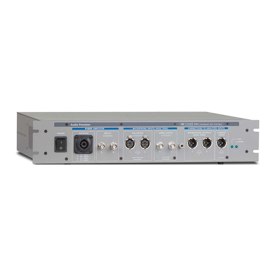
APx500 measurement software Output Functions Control of the APx1701 requires Audio Precision’s APx500 For output measurement functions, the APx1701 provides measurement software running on the measurement system an audio power amplifier that stands between a driven PC. - Page 32 Chapter : User’s Guide Mounting and ventilation The USB LED, to the left, indicates a number of APx1701 conditions, detailed in the following table. The APx1701 is designed to mount in a standard 19-inch relay rack, and is fitted with integral rack ears. The USB LED Condition APx1701 is two rack units (2 U) in height.
- Page 33 Chapter : User’s Guide resistance cable, such as the ground strap provided with the interface. DUT connections (amplifier outputs) Each channel of the two-channel audio power amplifier in the APx1701 has an output source resistance of approxi- mately 0.13 Ω, including the 0.10 Ω current sense resistor. When one channel is in use, the amplifier is rated at 100 W into 8 Ω, or 60 W into 4 Ω.
- Page 34 Chapter : User’s Guide DUT connections (microphone Solid-state condenser microphones typically use the +48 V phantom power system, which can be provided by the inputs) APx1701. See Microphone Powering on page 22. The APx1701 is designed to easily interface with common Unpowered professional microphones, such as dynamic or measurement microphones, and with common professional ribbon microphones, can be connected to the balanced...
- Page 35 Chapter : User’s Guide APx1701 current sense output must also be connected to an Testing a loudspeaker driver analyzer balanced input. Additionally, a low-resistance ground strap should be con- nected between the chassis grounds of the APx analyzer and the APx1701. APx1701/APx analyzer system interconnections Simplified diagram for acoustic testing and impedance...
- Page 36 Chapter : User’s Guide phone stand, and connect it to the APx1701. See Micro- Testing two loudspeakers simultaneously phone Connections on page 16. In many cases you may want to place the driver and the microphone in an acoustic chamber with a specified dis- tance between them;...
- Page 37 Chapter : User’s Guide Testing a loudspeaker (near field/far field) Testing headphones Simplified diagram for acoustic Simplified diagram for acoustic testing of stereo headphones testing and impedance using a headphone fixture. measurement of a loudspeaker driver using near- and far-field microphones. Mount the headphones to a fixture, and connect the APx1701 amplifier output channels to the headphones.
- Page 38 Chapter : User’s Guide phones in the fixture, and connect them to the APx1701. Comparing two microphones See Microphone Connections on page 16. In the APx500 software, set the Signal Path I/O to Trans- ducer Interface, and run the Acoustic Response measure- ment.
- Page 39 Chapter : User’s Guide (DUT) on a microphone stand, and connect it to the Testing a microphone with split IMD signals APx1701. See Microphone Connections on page 16. In the APx500 software, set the Signal Path I/O to Trans- ducer Interface, and run the Acoustic Response measure- ment.
- Page 40 Go to the Audio Precision Web site and download the A phantom powered microphone may be pre-polarized, or APx500 Series Self-Test from the Software: Utilities, Proj- may develop the polarization voltage internally from the ects &...
- Page 41 The SLFT-1701 should only be used with an APx-1701 and APx analyzer, using the dedicated Audio Precision self-test program, SelfTest.exe. The SLFT-1701 should only be used with this dedicated test.
- Page 42 Chapter : User’s Guide APx1701 Transducer Test Interface: User’s Guide...
Need help?
Do you have a question about the APx1701 Series and is the answer not in the manual?
Questions and answers