Table of Contents
Advertisement
Advertisement
Table of Contents

Summary of Contents for National Auto Tools NSS8XLT
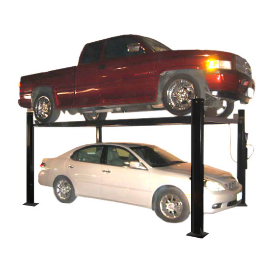
- Page 1 NSS8XLT Installation Manual NSS8XLT Installation Manual...
- Page 2 ATTENTION By following the instructions in this manual you can save yourself much time, frustration and money. The installation of your lift will take 4-5 hours. Do not rush. It is better to spend a few extra minutes and do the job right. If you will avoid the following common mistakes your lift will go together easily and serve you well for many years.
- Page 3 IMPORTANT SAFETY INSTRUCTIONS Read these safety instructions entirely! Failure to read these instructions may result in injury to user, other people within the area of the lift, or vehicles. We are not responsible for any injury or damage as a result of neglecting to carefully read and follow these instructions.
- Page 4 DANGER! The power unit used on this lift contains high voltage. Disconnect power at the receptacle before performing any electrical repairs. Secure plug so that it cannot be accidentally plugged in during service. WARNING! RISK OF EXPLOSION. This equipment has internal arcing or sparking parts which should not be exposed to flammable vapors.
- Page 5 installation manual in its entirety before attempting to install or operate the lift. SELECTING SITE: Before installing your new lift, check the following. OVERHEAD OBSTRUCTIONS: The area where the lift will be located should be free of overhead obstructions such as heaters, building supports, electrical lines etc.
- Page 6 COLUMN & CROSSRAIL INSTALLATION Lay down rear columns. Position the crossrail at the top of the two columns. (both cross rails are the same ) Install the crossrail in the column by sliding the plastic guide blocks into the column channel.
- Page 7 Find the leg caps (4 each), 1/2” x 7” bolts (4 each), 1/2” x 1 1/4” bolts (4 each), 1/2” nuts (8 each) and 1/2 “ flat washers (16 each), holes for cable face towards the center of the lift. Secure the leg caps with 1/2” x 1 1/4” bolts. Place the bolts with washers in through channel and secure with washers and nuts on the outside of the leg.
- Page 8 threaded end of the 1/2” x 50” (1/2” x 70” for the XLT) bent rod and the threaded end of the 1/2” x 126” straight safety latch linkage rod. Install the 1/2” x 50” (70” XLT) bent safety latch linkage rod into the main side track adjacent to back end of the cylinder (opposite the cylinder rod).
- Page 9 Start Up: Make sure power unit reservoir is full with 12 quarts of 10-wt hydraulic oil and spray the inside of the columns where the slide blocks glide with a light lubricant. 2) If you are not familiar with electrical hooks, it is best to call a certified electrician.
- Page 10 2. Stand clear - Push the top UP button to raise vehicle to desired height. Push the rod handle on the power unit to open release valve and lower tracks until it stops, check the all four latches for full engagement in the rack on each leg. 3.
Need help?
Do you have a question about the NSS8XLT and is the answer not in the manual?
Questions and answers