Table of Contents
Advertisement
Advertisement
Table of Contents

Summary of Contents for TSPROF K-02
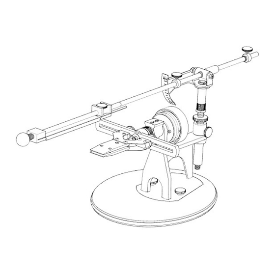
- Page 1 TSPROF K-02 Knife Sharpener E N G L I S H USER’S MANUAL...
-
Page 3: Table Of Contents
Table of Contents Table of contents ..................3 Safety guide ....................4 Maintenance tips ..................5 Components list ..................7 Assembling ....................7 Installation ....................8 Base unit assembling .................10 Abrasive Holder assembling ...............11 Installation of the Clamps ..............13 Adjustment of the rotary gear fi xation effort ........13 Installation of the Single Clamp ............14 Installation of the Double Clamp ............15 Installation of an abrasive ..............16... -
Page 4: Safety Guide
Safety guide WARNING • Before using, read this user’s manual to ensure correct usage through understanding. After reading, store it in a safe place for future refer- ence. Incorrect handling of this product could possibly result in personal injury or physical damage. The manufacturer assumes no responsibility for any damage caused by mishandling that is beyond normal usage defi... -
Page 5: Maintenance Tips
Maintenance tips • Moving the abrasive holder bar during the process of sharpening should be smooth and even, without any jerky motions and too much of a hand force applied. • When the sharpening is fi nished, remove the holder bar, abrasive and a knife. -
Page 8: Installation
Installation method - 1 1. Stick softening spacers from the spare parts to the G-clamp contact sur- faces. 2. Attach the body to a table using the G-clamp. - Page 9 Installation method - 2 1. Stick 5 self-adhesive silicone feet from the spare parts to the underside of the stand. 2. Place the sharpener body into the hollow part of the stand. Attach by tightening the thumbscrews. The stand should be placed on a fl at stable surface at some distance from a table edge.
-
Page 10: Base Unit Assembling
Base unit assembling 1. Loosen the thumb- screw fi xing the vertical bar. 2. Lubricate the vertical bar with a drop of a liq- uid grease and install it. -
Page 11: Abrasive Holder Assembling
3. Tighten the thumb- screw fi xing the vertical bar. Abrasive Holder assembling 1. Assemble the abrasive holder. - Page 12 2. Remove the outermost stopper and its bumper. 3. Lubricate the guide with a drop of a liquid grease and install the abrasive holder into the vertical bar bush.
-
Page 13: Installation Of The Clamps
4. Install the bumper and the stopper back to their places. Adjustment of the rotary gear fi xation eff ort Note: should tighten calibration wheel only with your hands, tightening too much may damage the rotary gear. Note: Be aware of rotary gear trigger- ing when the force is applied to a blade during the process of sharp- ening. -
Page 14: Installation Of The Single Clamp
2. Turn the rotary gear clockwise. Installation of the Single Clamp 1. Install the clamp into the frame and tighten it with the fi xing screws. -
Page 15: Installation Of The Double Clamp
Installation of the Double Clamp 1. Install the clamp jaws into the frame. Slightly tighten the fi xing screws. 2. Adjust the jaws position according to the length and geometry of a knife blade and tighten the fi xing screws. -
Page 16: Installation Of An Abrasive
Installation of an abrasive 1. Loosen the fi xing thumbscrew on the second thrust bar. -
Page 17: Calibration Of The Sharpening System And Clamps
2. Moving the second thrust bar, set the distance between the thrust bars to 10 - 12mm less than the abrasive length. Tighten the fi xing thumbscrew on the second thrust bar. 3. Pulling the fi rst thrust bar towards the handle, squeeze the spring and insert the abrasive. -
Page 18: Calibration Of Horizontal Frame Method 1
Required tools: spanners - 7mm, 10mm and 24mm, hex keys - 2mm, 2.5mm or torx - t8, t10. If an angle deviation is <= 0.3° (or other value of required accuracy), then an adjustment is not needed. Minor deviation calibration is not recommended. All the calibrations should be performed on a rigid stable surface. - Page 19 3. Place the digital gauge on the frame. If the gauge shows a deviation of <= 0.3° (or other value of required accuracy), adjustment is not needed. Next steps are needed to perform the calibration. 4. Holding the frame clutch with a 24mm spanner, loosen the fi xing nut with a 10mm spanner.
- Page 20 5. By turning the frame, adjust its position. 6. Holding this position with a 24mm spanner, tighten the fi xing nut with a 10mm spanner.
-
Page 21: Calibration Of Horizontal Frame Method 2
Calibration of horizontal frame - Method 2 Tools required: a ruler, spanners - 24mm and 10mm. 1. By turning the calibration wheel, set a slight rotary gear fi xation effort. 2. Position a ruler straight vertically. Measure the distance from the ends of the frame to a table. - Page 22 3. Holding the frame clutch with a 24mm spanner, loosen the fi xing nut with a 10mm spanner. 4. By turning the frame, adjust its position so the measured distances are about equal.
- Page 23 5. Holding this position with a 24mm spanner, tighten the fi xing nut with a 10mm spanner.
-
Page 24: Turning Clamp Angle Calibration
Turning Clamp angle calibration Calibration should be made to eliminate angle asymmetry when the clamp rotates, which may emerge during transportation or after a long operation period. Tools required: a digital gauge, hex key. 1. Loosen the holding screws. 2. Take a fl at rigid plate 15 - 30mm wide, 1.5 - 3mm thick, and 100 - 200mm long. - Page 25 3. Install the plate into the clamp. 4. Tighten the front holding screws slightly; fi nal tightening should be made at the back screw.
- Page 26 5. Thus, the jaws of the clamp should be parallel. 6. Place the digital gauge on the plate along the clamp’s rotation axis and reset its value.
- Page 27 7. Flip the clamp over. 8. Make a measurement. The gauge will show the angles difference when the clamp is fl ipped. If the deviation is <= 0.3° (or other value of required accuracy), adjustment is not needed.
- Page 28 9. Loosen the screws to level this difference. Adjust the angle manually until the gauge value is 1/2 of the difference measured before. 10. Holding this gauge value, tighten the screws.
-
Page 29: Digital Gauge Platform Horizontal Calibration
11. Repeat the procedure in order to ensure an accurate setting. Digital gauge platform horizontal calibration 1. Place the digital gauge on the sharpener’s base unit and reset its value. - Page 30 2. Place the digital gauge on the digital gauge platform. If the deviation is <= 0.3° (or other value of required accuracy), adjustment is not needed. Next steps are needed to perform the calibration. 3. Loosen the calibration screw with a 2mm hex key or torx t8, half-turn is enough.
- Page 31 4. Holding the digital gauge platform with a hand from below and pressing it up, adjust its angle according to the digital gauge value. 5. Keep holding the platform in the chosen position, remove the digital gauge and tighten the calibration screw.
-
Page 32: Digital Gauge Platform Parallel Calibration
Digital gauge platform parallel calibration This calibration is performed after the Turning Clamp angle calibration. 1. Place a digital gauge onto the plate and reset its value. 2. Place a digital gauge on the digital gauge platform strictly as it’s shown in the fi... - Page 33 The gauge will show the angle difference. If the deviation is <= 0.3° (or other value of required accuracy), adjustment is not needed. Next steps are needed to perform the calibration. 3. Adjust the inclination of the platform to minimize the deviation. Use a 2mm hex key or torx t8 to set its angle according to the digital gauge value.
-
Page 34: Knife Installation
Installation of a knife into the Single Clamp 1. Loosen front and back holding screws. 2. Stick a piece of leather or masking tape on the place of contact with the jaws in order to avoid damage to polished or coated knives. - Page 35 3. Install a knife into the clamp. 4. Tighten the front holding screws slightly; fi nal tightening should be made at the back screw.
-
Page 36: Knife Installation Into The Double Clamp
Loosen the tightening screws inversely to remove the knife. Installation of a knife into the Double Clamp 1. Adjust the jaws position according to the length and geometry of the knife blade and tighten the fi xing screws. -
Page 37: Full Fl At Grind Clamping
2. The rest clamping steps are the same as in the Single Clamp installa- tion. Full fl at grind clamping 1. Install a knife into the clamp. - Page 38 2. First - tighten the front holding screws slightly, then tighten the back one. 3. Loosen the front holding screws slightly.
- Page 39 4. Tighten the back screw a little bit more. 5. Thus, the jaws will settle at an angle to each other, as shown in the fi gure.
-
Page 40: Calibration Of The In-Built Gauge
Calibration of the in-built gauge 1. Install the digital gauge on the digital gauge platform. Arrange the device as shown in the fi gure and reset it. 2. Install the digital gauge on the abrasive holder’s reference plate. - Page 41 3. Loosen the screw at the back of the in-built gauge pointer. 4. Incline the bar until the digital gauge displays zero or a minimal value.
- Page 42 5. Holding the bar in this position, turn the pointer to the 0 mark on the angle gauge. 6. Tighten the screw at the back of the pointer.
-
Page 43: Sharpening Angle Adjustment
Adjustment of the sharpening angle 1. Install an abrasive and lean it against the cutting edge. Pay attention that the abrasive thickness affects the sharpening angle. 2. Loosen the thumbscrew on the vertical angle bar to set the required angle approximately by moving it up and down. Tighten the thumbscrew back. - Page 44 3. Loosen the lock-nut. 4. Turn the fi ne adjustment screw and set the exact sharpening angle.
-
Page 45: Bar Stoppers Adjustment
5. Tighten the lock-nut back. Bar stoppers adjustment 1. The stoppers are adjusted after setting the sharpening angle. Loosen the near stopper and position the near abrasive edge against the cutting edge of a blade as it’s shown in the fi gures. - Page 46 1. Holding the abrasive in this position, move the stopper to the bush and tighten its thumbscrew.
- Page 47 The procedure for the second stopper is the same.
-
Page 48: Bar Parking
Bar parking 1. When the abrasive is not in use, the bar can be parked. Turn the near bar stopper’s thumbscrew downwards, as indicated in the fi gure. - Page 49 2. Slide the bar against the stop and release it.
- Page 50 ТехноСтудия “Профиль” 426000, Россия, г. Ижевск 10 лет Октября 60, офис 405, БЦ “Нова Парк” Телефон: +7(3412)640-701, +7(3412)566-628 E-mail: info@tsprof.com сайт производителя: tsprof.com интернет магазин: shop.tsprof.com Настоящая Инструкция по эксплуатации содержит сведения на октябрь 2016 года.
Need help?
Do you have a question about the K-02 and is the answer not in the manual?
Questions and answers