
Summary of Contents for Bodyguard i-Tag
- Page 1 -Tag BodyGuard ® Driver Awareness System SAFETY SOLUTIONS Installation Guide BodyGuard Safety Solutions—A division of Orbit Communications Pty Ltd Install Guide rev r1.11 Page...
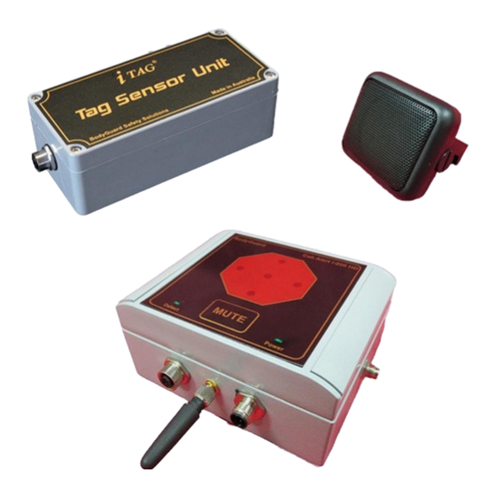
- Page 2 Driver Awareness System SAFETY SOLUTIONS Introduction This Guide provides information to assist with installation and use of the BodyGuard® i-Tag® proximity detection and warning system. The document begins with an overview of the system and then describes the wiring connections for both single sensor and dual sensor systems.
- Page 3 Dual sensor systems are supplied with a “Y” splitter cable that enables the 2 sensors to plug into the one Cab Alert unit connector. The supplied cable is Alpha Wire 2466C or 1243/2C. BodyGuard Safety Solutions—A division of Orbit Communications Pty Ltd Install Guide rev r1.11 Page...
- Page 4 BOTH ends of the cable (i.e. Straight-Through connection). Wire colouring Pin 1: Pin 2: White Pin 3: Green Pin 4: Black RED/Black = shielded twisted pair White/Green = shielded twisted pair BodyGuard Safety Solutions—A division of Orbit Communications Pty Ltd Install Guide rev r1.11 Page...
-
Page 5: Power Cable Connections
When logging is not required, “Ignition Sense” connects to 12V DC input signal. IMPORTANT: Tag Detection will only occur when the WHITE “Ignition Sense” wire connects to the supply voltage. 12/24V DC supply, NO logging BodyGuard Safety Solutions—A division of Orbit Communications Pty Ltd Install Guide rev r1.11 Page... - Page 6 -Tag BodyGuard ® Driver Awareness System SAFETY SOLUTIONS 12/24V DC supply, with Data Logging Higher than 24V DC supply, NO logging BodyGuard Safety Solutions—A division of Orbit Communications Pty Ltd Install Guide rev r1.11 Page...
- Page 7 -Tag BodyGuard ® Driver Awareness System SAFETY SOLUTIONS Higher than 24V DC supply, with logging BodyGuard Safety Solutions—A division of Orbit Communications Pty Ltd Install Guide rev r1.11 Page...
-
Page 8: Switched Output
Tag detection. An external relay can be connected to control warning devices or “lockout” controls. A protection diode (such as 1N4001 or 1N4007) should be placed across the relay control coil as shown. BodyGuard Safety Solutions—A division of Orbit Communications Pty Ltd Install Guide rev r1.11 Page... - Page 9 Enclosure when bolts fastened. If the pivot is not used then ensure that the thread of bolts used does not extend more than 10mm into the enclosure. BodyGuard Safety Solutions—A division of Orbit Communications Pty Ltd Install Guide rev r1.11...
-
Page 10: Sensor Location
In this case, try to mount sensor at least 30mm above the surface. Free space Free space Free space Free space At least 40mm if not using supplied magnets Free space BodyGuard Safety Solutions—A division of Orbit Communications Pty Ltd Install Guide rev r1.11 Page... - Page 11 80-90% distance Approximate 3D Detection zone pattern Aerial View This image demonstrates the effect of placing sensor horizontally for detection zone pattern. Actual distance may be vary. BodyGuard Safety Solutions—A division of Orbit Communications Pty Ltd Install Guide rev r1.11 Page...
- Page 12 Approximate 3D Detection zone pattern Aerial View This image demonstrates the effect of placing sensor vertically for detection zone pattern. Actual distance may be vary BodyGuard Safety Solutions—A division of Orbit Communications Pty Ltd Install Guide rev r1.11 Page...
- Page 13 The example below illustrates how multiple sensors provide extended range at front and rear of larger vehicle with Sensors mounted horizontally. Distances shown are indicative to highlight shape of zone only. BodyGuard Safety Solutions—A division of Orbit Communications Pty Ltd Install Guide rev r1.11 Page...
- Page 14 The example below illustrates how multiple sensors provide extended range at front and rear of larger vehicle when sensors mounted vertically. Distances shown are indicative to highlight shape of zone only. BodyGuard Safety Solutions—A division of Orbit Communications Pty Ltd Install Guide rev r1.11 Page...
- Page 15 Single system Sensors and dual “Front” Sensors; set ID = “0”. Dual system “Rear” Sensors; set ID = “1”. NOTE: Single system MUST have Sensor ID set to “0”. Front Rear BodyGuard Safety Solutions—A division of Orbit Communications Pty Ltd Install Guide rev r1.11 Page...
-
Page 16: Configuration Software
When ignition is switch back on, the system will power up and start detection. BodyGuard Safety Solutions—A division of Orbit Communications Pty Ltd Install Guide rev r1.11... -
Page 17: Alarm Activation
2. Tag “Disable Pouch”. This pouch mounts to the vehicle. Tags disable while in the pouch and automatically enable when removed. The driver places the Tag into pouch when operating the vehicle and then removes the Tag when leaving the vehicle. BodyGuard Safety Solutions—A division of Orbit Communications Pty Ltd Install Guide rev r1.11 Page... -
Page 18: Safety Precautions
Important BodyGuard proximity detection and warning system is intended to be an aid to the driver and is not intended in any way to replace existing safety processes or remove or minimise the driver’s diligence and/or duty of care. - Page 19 Ensure cause of fuse “blowout” fixed before replacing fuse. Ensure Power supply input voltage to BodyGuard unit is within the range specified for the model (12V DC to 28V DC for standard model), (12V DC to 90 VDC when used with voltage reducer).
-
Page 20: Certificate Information
Changes or modifications not expressly approved by the party responsible for compliance could void the user's authority to operate the equipment. BodyGuard Safety Solutions—A division of Orbit Communications Pty Ltd Install Guide rev r1.11 Page...
Need help?
Do you have a question about the i-Tag and is the answer not in the manual?
Questions and answers