
Summary of Contents for Navico BSM-1
- Page 1 Installation Manual Navico BSM-1 Broadband Sounder Module English www.northstarnav.com. www.simrad-yachting.com Brands by Navico - Leader in Marine Electronics...
- Page 3 (2) this device must accept any interference, including interference that may cause undesired operation of the device. CE Declaration of conformity Hereby, Navico Holding AS declares that this BSM-1 is in compliance with the essential requirements and other relevant provisions of Directive 1999/5/EC.
- Page 4 Por medio de la presente Navico Holding AS declara que el BSM-1 cumple con los requisitos esenciales y cualesquiera otras disposiciones aplicables o exigibles de la Directiva 1999/5/CE. Navico Holding AS declara que este BSM-1 está conforme com os requisitos essenciais e outras provisões da Directiva 1999/5/CE.
- Page 5 Feedback from you Your feedback is important and helps Navico ensure that this manual is a valuable resource for all marine technicians. E-mail your comments or suggestions about this manual to the following address: tech.writing@navico.com...
-
Page 6: Table Of Contents
Mounting location ..........8 Mounting the BSM-1 module ......9 3 Connecting BSM-1 .......... 10 Connect the transducer ........11 Connect BSM-1 to your display ......12 Simrad NSE8/NSE12 ......... 12 Simrad GB40 / Northstar 8000i ......13 Connect power ..........15 BSM-1 Indicator lights ........ -
Page 7: Introduction
1 Introduction This document explains how to connect the Navico BSM-1 sounder module to a compatible navigation system or display unit. The BSM-1 connects directly between the transducer and display unit or with a network switch (Ethernet Linker). Read the following instructions carefully before attempting any installation. - Page 8 Part Number Description Item 003-8256-00 Installation kit including: 019-0009-00 Terminal plug 043-0037-00 Fuse BK/ATC-3 Fuse holder ATC 089-0431-00 BLD TYPE IN LINE Screw #10 X 3/4 083-0011-21 PN HD SS selftap 000-0127-51 1.5 m (5 ft) Ethernet extension cable 032-0167-02 Power cable 2 m (6.5 ft) 988-0170-08...
-
Page 9: Installation
You will need to attach the power cable, Ethernet cable and a transducer to the BSM-1. The transducer and Ethernet cables are not included. Do not run the transducer cabling near the BSM-1 DC power cables or any VHF antenna coax cables or any VHF DC power cables. -
Page 10: Mounting Location
Ensure you have as much separation as possible between different electrical equipment, (see diagram below). The BSM-1 conforms to the appropriate Electromagnetic Compatibility (EMC) standards but proper installation is required to get the best use and performance from this product. -
Page 11: Mounting The Bsm-1 Module
Mounting the BSM-1 module Preferably mount the BSM-1 module on a vertical surface so that cables exit downwards. Secure using suitable fasteners for the surface. 4 SS self tapping screws are supplied with the equipment. Installation | 9... -
Page 12: Connecting Bsm-1
Connect your transducer (see "Parts List" page 18) for a list of compatible transducers Removing the transducer cable from the BSM-1 while the module is powered on can cause sparks. Remove the transducer cable only after the module has been disconnected from its power source. -
Page 13: Connect The Transducer
Connect the transducer For a list of compatible transducers (see "Parts List" page 18), or contact your dealer. Transducer connector pin assignments Assignment Depth + Speed Speed power Temp. Depth - shield Temp / speed ground Connecting BSM-1 | 11... -
Page 14: Connect Bsm-1 To Your Display
Connect BSM-1 to your display The BSM-1 connects to your display over an Ethernet network, either directly or via an Ethernet network switch. Simrad NSE8/NSE12 12 | Connecting BSM-1... -
Page 15: Simrad Gb40 / Northstar 8000I
Connect power of BSM-1 to same power source as the display. If BSM-1 is connected directly to the display, it is important that the BSM-1 is powered on when the GB40 or 8000i is on so that the display can see a functioning network. C is a standard Ethernet cable. - Page 16 BSM-1 connection via Ethernet switch Description BSM-1 Ethernet adapter cable 5 pin to RJ45 (not included) Ethernet cable RJ45 type (not included) GB40 / 8000i NavComputer network port Navico 8 port Ethernet Linker AA010009 14 | Connecting BSM-1...
-
Page 17: Connect Power
Connect via a switch at console (not included) to turn off BSM- 1 when not in use. Battery 12 or 24 V DC (Max range 9-32 V DC) * BSM-1 connected GB40 or 8000i network via an Ethernet Linker. Connecting BSM-1 | 15... - Page 18 Doing so will prevent voltage drop. Voltage drop will not harm the module, but it can cause the BSM-1 to reset. If the BSM-1 resets, some information could be lost and it may change the operation mode of the unit.
-
Page 19: Bsm-1 Indicator Lights
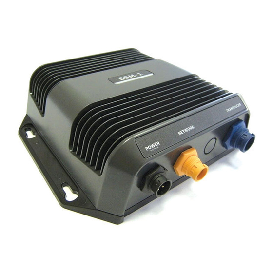
Code 3 Power red/green solid green solid red - blinking - all okay system red - internal starting error Network green traffic indicator Transducer green solid green blinking - all okay green - searching for signal Connecting BSM-1 | 17... -
Page 20: Parts List
4 Parts List Ethernet cables RJ45 type Part no Description AA010079 0.5 m (1.6 ft) AA010080 2 m (6.5 ft) AA010081 5 m (16.4 ft) AA010082 10 m (32.8 ft) Transducer options Below is a list of standard transducers. Consult your dealer for more information. -
Page 21: Optional Parts
10 m (32.8 ft) cable Optional parts Part no Description AA010009 Navico 8 port Ethernet Linker (RJ45 type) 000-0132-031 Navico NEP-1 4 port Ethernet Linker (HDS type - orange connector) 000-00022-001 Transducer adapter cable - 6 Pin LTW to 7 Pin BLUE 0.6 m (2 ft) - Page 22 2. Cable 000-10046-001 is simply a stripped wire adapter cable that can be used if you wish to cut the plug off of an existing transducer. We highly recommend a professional electronic technician hired to do this soldering work. A list of main transducers that can be accommodated is on our website (www.simrad-yachting.com www.northstarnav.com.
-
Page 23: Drawings
5 Drawings Drawings | 21... -
Page 24: Specifications
6 Specifications Electrical Voltage input 12 or 24 V DC (max range 9 V to 32 V DC) Output power 3,000+ feet at 250 Watts RMS Frequencies 50 kHz, 83 kHz, 200 kHz Communication Ethernet 10/100 Module dimensions Size: (HWD) 57 X 180 X 203.75 mm (2.24 X 7.09 X 8.02 in.) Weight: 0.9 Kg (2 lbs)
Need help?
Do you have a question about the BSM-1 and is the answer not in the manual?
Questions and answers