Table of Contents
Advertisement
Quick Links
Advertisement
Table of Contents

Summary of Contents for DENTIS LUVIS L200
- Page 1 Global TOP 10 in Healthcare LUVIS L200 USER’S MANUAL (V2.2) Mar/12/2018 Major Surgical Luminaire DENTIS CO., LTD. 99, Seongseoseo-ro, Dalseo-gu, Daegu, Korea Tel. 82-53-583-2804 FAX. 82-53-583-2806 www.dentis.co.kr / www.luvis.co.kr Please read this USER’S MANUAL before operating this equipment.
-
Page 2: Table Of Contents
CONTENTS 1. Standard ..................................... 4 2. Warning ...................................... 5 3. Symbol......................................7 4. Introduction ....................................9 4.1 Intended use ..................................9 4.2 General description ................................ 10 4.3 Environmental requirement ............................11 4.4 Safety information ................................11 4.5 Warranty regulation ............................... 12 4.6 Electromagnetic Compatibility ............................ - Page 3 6.6 MAIN HANDLE ................................. 24 6.7 Mobile Type..................................25 6.8 BATTERY PACK .................................. 26 7. Performance characteristic .............................. 26 7.1 L200 LIGHTHEAD on the SPRING ARM(STD) ......................27 7.2 OperOperating range of HEAD ARM .......................... 27 8. Sterilization and Cleaning ............................... 28 8.1 Sterilization..................................
-
Page 4: Standard
1. Standard Ÿ Certification of DENTIS ISO 9001:2008 • • EN ISO 13485:2012 Relevant EC Directives: 93/42/EEC Medical Device Directive as amended by • 2007/47/EC, Annex I and Annex VII. Ÿ Applied Standards: • EN ISO 15223-1:2012, Medical devices – Symbols to be used with medical device labels, labelling and information to be supplied •... -
Page 5: Warning
To protect against the risk of electrocution, connect the power cables carefully. WARNING Major Surgical Luminaire(LUVIS L200) is class I equipment. In order to avoid the risk of an electric shock, the equipment must be connected to a mains supply with PE(protective earth). - Page 6 However, DENTIS takes no responsibilities of the results caused by default, omission, or misuse of it. WARNING DENTIS has rights to modify the product itself or specifications of the product without any prior notice, as well as rights not to renew that modification on this manual.
-
Page 7: Symbol
3. Symbol Ÿ The following symbols are used in the equipment and/or in this manual. Symbol Meaning CE label The device bears the CE mark and complies with the requirements of European Directive 93/42/EEC Medical Device Directive as amended by 2007/47/EC, Annex I and Annex VII. - Page 8 Fragile symbol This side up Handle with care symbol Do not build up more than 5 boxes Manufacture Europe Representative Manufacture Date Temperature between 0˚C ~ 40˚C Humidity between 0%RH ~ 80%RH Professional LED Light System for All of Surgery Application...
-
Page 9: Introduction
4. Introduction 4.1 Intended use Ÿ Major Surgical Luminaire (L200) is intended to be used to provide visible illumination of the surgical area or the patient during surgical operations, diagnosis and treatment. Ÿ Classification under the provision of 93/42/EEC(MDD) : Class I - Major Surgical Luminaire (L200) is classified as a Class I device. -
Page 10: General Description
Ÿ The user must ensure that that the device works properly and is in a satisfactory condition before each use. Ÿ This DENTIS device is intended only for use in the field of medical. It is impermissible to use the device for a purpose for which it was not intended. -
Page 11: Environmental Requirement
4.3 Environmental requirement Ÿ Conditions of the usage environment ž Temperature : 0 ºC - 40 ºC ž Humidity : R.H. 30 % - R.H. 90 % ž Atmospheric pressure: 0 - 2,000 m (106 – 80 Kpa) Ÿ Conditions of the transportation environment ž... -
Page 12: Warranty Regulation
Ÿ DENTIS warrants all products against defects in materials or workmanship for one year from time of delivery. Ÿ DENTIS’s sole obligation under the warranty is to provide parts for the repair, or at its option, to provide the replacement product (excluding labor). - Page 13 Harmonic emissions Complies The L200 is suitable for use in all establishments other than IEC 61000-3-2 domestic premises and those directly connected to the public Voltage Complies low-voltage power supply network that supplies buildings fluctuations/ used for domestic purposes. flicker emissions IEC 61000-3-3 Guidance and manufacturer’s declaration - Electromagnetic immunity Ÿ...
- Page 14 Ÿ Guidance and manufacturer’s declaration - Electromagnetic immunity The L200 is intended for use in the electromagnetic environment specified below. The customer or the user of the L200 should assure that it is used in such an environment. Immunity IEC 60601 Compliance Electromagnetic environment - guidance test...
- Page 15 Recommended separation distances between portable and mobile RF Ÿ communications equipment and the L200 The L200 is intended for use in an electromagnetic environment in which radiated RF disturbances are controlled. The customer or the user of the L200 can help prevent electromagnetic interference by maintaining a minimum distance between portable and mobile RF communications equipment (transmitters) and the L200 as recommended below, according to the maximum output power of the communications equipment.
-
Page 16: Lighthead Specification
5. LIGHTHEAD specification 5.1 Technical specification (In accordance with IEC 60601-2-41) Ÿ STANDARD SPECIFICATION Specifications Unit LUVIS L200 Remark Normal Mode Central illuminance Ec (@1m) 160,000 Electronic adjustment range 25 ~ 100 Light field diameter d10 20 ~ 30 Light field diameter d50... -
Page 17: Electrical Specification (In Accordance With Iec 60601-1)
5.2 Electrical specification (In accordance with IEC 60601-1) Ÿ SMPS TECHNICAL DATA Content Single LIGHTHEAD Dual LIGHTHEAD AC 100 – 240 V, 50/60 Hz AC 100 – 240 V, 50/60 Hz Input (1.8/0.8 A typical at AC 115/230 V (1.8/0.8 A typical at AC 115/230 V full load) full load) x 2 Output... -
Page 18: Internal Camera(Optional) Specification
660 x 660 14.8 2Axis MOBILE ARM 28.4 Except SPRING ARM L x W x H : BATTERY PACK 244 x 164 x 120 * SPRING ARM Type of Internal Camera : AC 2000(W/S) 5.4 Internal Camera(optional) specification Content Specifications REMARK Image Sensor 1/2.8 type Exmor CMOS... -
Page 19: Use
6. USE 6.1 ARM CONTROLLER Ÿ The LIGHTHEAD can be controlled using the ARM CONTROLLER FUNCTION LUVIS L200 Press to turn on, press and hold (2 • Second) to turn off. On/Off button The light turns on, at the last illumination •... -
Page 20: Handle Touch Controller
6.2 HANDLE TOUCH CONTROLLER Ÿ The LIGHTHEAD can be controlled using the HANDLE TOUCH CONTROLLER The control panel of the HANDLE TOUCH CONTROLLER LUVIS L200 Light field diameter ① Ÿ The light field diameter decreases. level down button Light field diameter ②... -
Page 21: Wall Control Box(Optional)
6.3 WALL CONTROL BOX(optional) Note: The control panel depends on the configuration installed. Wall CONTROL BOX LIGHTHEAD 1 control panel LIGHTHEAD 2 control panel LIGHTHEAD 1 SMPS LIGHTHEAD 2 SMPS The control panel of the WALL CONTROL BOX ⑤ ② ⑥... -
Page 22: Controlling The Internal Camera(Optional)
6.4 Controlling the INTERNAL CAMERA(optional) Ÿ The INTERNAL CAMERA can be controlled using the ARM CONTROLLER or WALL CONTROL BOX. FUNCTION LUVIS L200 INTERNAL CAMERA Press to turn on, press and hold (2 • Second) to turn off. On/Off Button The light turns on, at the last illumination •... -
Page 23: Positioning
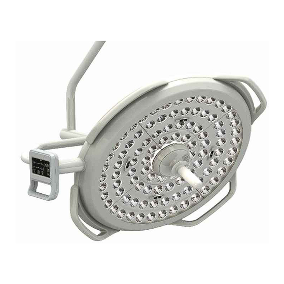
6.5 Positioning Positioning the L200 LIGHTHEAD SIDE HANDLE MAIN HANDLE HANDLE Ÿ Use the MAIN HANDLE or SIDE Ÿ Recommended distance : 1m HANDLE to position the L200 LIGHTHEAD before the operation. Ÿ This MAIN HANDLE can be removed for sterilization. -
Page 24: Main Handle
6.6 MAIN HANDLE WARNING After each sterilization and before using the MAIN HANDLE again : Ÿ Check for cracks. Ÿ Check that the MAIN HANDLE click into place correctly on the LIGHTHEAD. * INTERNAL CAMERA PUSH CAMERA COVER BUTTON MAIN HANDLE HANDLE Attaching the MAIN HANDLE Detaching the MAIN HANDLE... -
Page 25: Mobile Type
6.7 Mobile Type WARNING The mains plug should not be difficult to remove, place it in position (Means for isolation is disconnect mains plug) LIGHTHEAD Ÿ While moving the mobile type for use, please fold the spring arm as much as possible and hold the AC2000 MOBILE SPRING ARM by AC2000 MOBILE hands. -
Page 26: Battery Pack
6.8 BATTERY PACK WARNING The lithium–ion BATTERY PACK is a consumable item and should be replaced every 12 months by service personnel.(It can vary depending on the number of use.) Check the BATTERY PACK capacity level by pushing the BATTERY CHECK BUTTON. WARNING The mains plug should not be difficult to remove, place it in position (Means for isolation is disconnect mains plug) -
Page 27: Performance Characteristic
7. Performance characteristic 7.1 L200 LIGHTHEAD on the SPRING ARM(STD) 7.2 OperOperating range of HEAD ARM WARNING If this device is operated beyond the indicated angles, it can be damaged. During positioning, eventual collisions between the LIGHTHEAD, SPRING ARMs and other devices must be avoided. -
Page 28: Sterilization And Cleaning
8. Sterilization and Cleaning 8.1 Sterilization WARNING Before using MAIN HANDLE or SENSOR COVER SEALING, please conduct a sterilization treatment. The requirements of the national committees (standards and directives) for disinfection must be observed. MAIN HANDLE CAMERA COVER OUT SENSOR COVER SEALING Sterilization Ÿ... -
Page 29: Maintenance
9. Maintenance WARNING A electrical and mechanical check-up should be done every year. Disconnect the pendant system from the mains before any maintenance work to prevent electric shock. WARNING Check points on maintenance work - Defects of paint - Plastic fissures - Loosened parts. -
Page 30: Troubleshooting
10. Troubleshooting L200 Product Problem Cause Corrective action Power cut Check if supply mains are operating. Does not working of a backup power Please contact your supplier. If the LED light on supply(UPS). the LIGHTHEAD Press the stand-by button of the control does not turn on. - Page 31 Cleanse it with designated chemicals If the SAFETY (Alcohol, Ethanol). COVER of the If the essential performances of the Pollution LIGHTHEAD is device (Intensity of Illumination, Color polluted. Temperature) are seriously impaired, please contact your supplier. Internal Camera(optional) Problem Cause Corrective action Power cut Check if supply mains are operating.
-
Page 32: Disposal
- The electrical boards should be submitted to an appropriate recycling proceeding - The cardboard box may be recycled with other paper products. Please contact the closest DENTIS branch or your supplier, if you have any Ÿ questions about recycling of the device. -
Page 33: Model Designation
12. Model designation a: No. e: Internal Camera i: LED Colour m: Camera S=Single, M=Multi, 0=No CAM, 1=Internal, D=Single & Multi 2=External b: Type f: Wall Controller j: Head Arm Axis n: Wall Controller A=3Axis, B=2Axis 0=No WC, 1=WC c: Combination g: Battery k: Mount Type o: Battery S=Single Ceiling,... - Page 34 a: No. e: Internal Camera M200 i: LED Colour m: Camera S=Single, M=Multi, 0=No CAM, 1=Internal, D=Single & Multi 2=External b: Type f: Wall Controller j: Head Arm Axis n: Wall Controller A=3Axis, B=2Axis 0=No WC, 1=WC c: Combination g: Battery k: Mount Type o: Battery S=Single Ceiling,...
-
Page 35: List Of Component
13. List of component CENTRAL AXIS CEILING TUBE AC2000 SPRING ARM(NRH) AC2000 SPRING ARM(STD) SMPS CEILING COVER & CEILING COVER BRACKET L200 LIGHTHEAD(3Axis) L200 LIGHTHEAD(2Axis) Professional LED Light System for All of Surgery Application... - Page 36 L200 LIGHTHEAD WALL CONTROL BOX (Optional) (Include Optional Internal Camera) BATTERY PACK (Optional) MOBILE ARM Professional LED Light System for All of Surgery Application...
-
Page 37: Manufacturer And Factory
14. Manufacturer and Factory Manufacture : DENTIS CO., LTD. Ÿ 99, Seongseoseo-ro, Dalseo-gu, Daegu, Korea Factory : DENTIS MEDICAL DIVISION Ÿ 6, Yuram-ro, Dong-gu, Daegu, Korea Professional LED Light System for All of Surgery Application... -
Page 38: Europe Representative
15. Europe Representative Location of EC REP Ÿ CALMED INVEST Kft. Address : 1191 Budapest, Attila utca 34., Budapest, Hungary Professional LED Light System for All of Surgery Application... - Page 39 www.luvis.co.kr Please read this USER’S MANUAL before operating this equipment.
Need help?
Do you have a question about the LUVIS L200 and is the answer not in the manual?
Questions and answers