Advertisement
UDT - Universal Defrost Timer
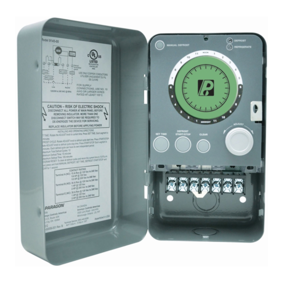
Universal Defrost Timer (UDT)
The Universal Defrost Timer family consists of two models: electric defrost and off-cycle defrost. Both models can
be wired directly to 120V AC, 208V AC or 240V AC power sources. The timers can be used in place of traditional
electromechanical defrost time clocks. Users should review this document, including terminal specifications, to ensure
compatibility with the application.
The timer maintains and displays the current time and each defrost cycle. The user can glance at the display and
immediately determine what time it is as well as see the defrost settings (start time and duration). In
addition, colored LEDs indicate the current system mode (refrigeration or defrost).
1
Advertisement
Table of Contents

Summary of Contents for Robertshaw Paragon 9145
- Page 1 UDT - Universal Defrost Timer Universal Defrost Timer (UDT) The Universal Defrost Timer family consists of two models: electric defrost and off-cycle defrost. Both models can be wired directly to 120V AC, 208V AC or 240V AC power sources. The timers can be used in place of traditional electromechanical defrost time clocks.
-
Page 2: Operation And Functions
Operation is subject to the following two conditions: (1) This device may not cause harmful interference, and (2) this device must accept any interference received, including interference that may cause undesired operation. Changes or modifications not expressly approved by Robertshaw Controls could void the user’s authority to operate the equipment. -
Page 3: Canadian Compliance
Robertshaw. • It is the responsibility of the installer and the user to assure that the application and use of Robertshaw products are in compliance with all federal, state and local requirements, including, without limitation, all requirements imposed under the National Electric Code and any applicable building codes. - Page 4 NOTE: For models 9045-00M and 9145-00M: Place the peel-and-stick label (3.25” x 7”), over the old label on the inside cover of the metal enclosure used by the 8100 or 8200 series of products. Mounting Dimensions – Metal Case Fig. 1 Overall Dimensions Fig.
- Page 5 Representative Wiring Installation Procedure Model 9045 Connecting the refrigeration / defrost equipment (See Figures 3 and 4) NOTE: Rated input power 120/208-240V AC 50/60 Hz (+10,-15%) 1. Turn off the AC power. 2. Open the metal case to access the control connectors. 3.
-
Page 6: Control Wiring
Control Wiring All wiring should conform to the National Electric Code and local regulations. NOTE: Use copper conductors only! • Electrical leads should not be taut; allow slack for temperature change and vibration. • The manufacturer suggests removal of the electronic controller prior to mounting the metal case to a wall or any flat surface to facilitate installation and the installation of conduit fittings and conduit installation. - Page 7 All wiring should conform to the National Electric Code and local regulations. NOTE: Use copper conductors only! • Electrical leads should not be taut; allow slack for temperature change and vibration. • The manufacturer suggests removal of the electronic controller prior to mounting the metal case to a wall or any flat surface to facilitate installation and the installation of conduit fittings and conduit installation.
- Page 8 Input Power: 120/208-240V AC 50/60 Hz (+10,-15%) Power Consumption: 6 VA max Defrost termination switch (terminal G) input impedance to terminal C: 85kΩ +/- 5% Operating Voltage: 120V AC (+10%, -15%) @ 50/60Hz 208V AC to 240V AC (+10%, -15%) @ 50/60Hz NOTE: There are no user-required adjustments to switch between the high and low voltage.
- Page 9 MODEL 9145 Graphic Description / Dimensions System Status Display Layout Indicators Initiate 15 Minute Manual Defrost Lighted Display Display shows defrost start time and duration Easy Set Up Set Time, Set Defrost Start and Defrost End Direct Connect Line Voltage – 120/208/240V AC...
-
Page 10: Manual Defrost
Programming Upon initial power up the flashing segment should be at 12:00 pm (noon). Turning the ADJUST knob will activate the programming cursor and momentarily turn off the time. If any of the other segments are on (lit), they may be related to a previous program. The display backlight will turn on when the ADJUST knob is turned. The backlight remains lighted for 10 seconds after the last activity. -
Page 11: Troubleshooting
Short Cycle Protection The control will not schedule a compressor run (ON) time shorter than five minutes. The control will not schedule a compressor OFF time shorter than thirty seconds except for loss of power situations. The operator can stop or start the compressor at any time. Program Carryover Time will be retained for a minimum of 100 hours;... - Page 12 Robertshaw®, Ranco®, Paragon® and Uni-Line® are Customer Service Telephone 1.800.304.6563 For Technical Service trademarks of Robertshaw, its subsidiaries and/or www.robertshaw.com affiliated companies. All other brands mentioned ©2016 Robertshaw Customer Service Facsimile 1.800.426.0804 Telephone 1.800.445.8299 HVACCustomerService@robertshaw.com TechnicalService@robertshaw.com may be the trademarks of their respective owners.
Need help?
Do you have a question about the Paragon 9145 and is the answer not in the manual?
Questions and answers