Table of Contents
Advertisement
Quick Links
Advertisement
Table of Contents

Subscribe to Our Youtube Channel
Related Manuals for Terex AL4000D2 Series

Summary of Contents for Terex AL4000D2 Series
- Page 1 November 2006 OPERATOR/SERVICE & PARTS MANUAL Series AL4000D2 Light Tower PART NUMBER 833002 REVISION A November 2006 TOLL FREE 800-433-3026 P.O. BOX 3147 FAX (Parts Dept) 800-633-5534 ROCK HILL, S.C. 29732 USA Part No. 833002 Rev A AL4000 Light Tower...
-
Page 2: Table Of Contents
November 2006 TABLE OF CONTENTS OPERATOR’S MANUAL To the Operator ........................ 4 Safety Alert Symbols ......................5 General Safety ......................6-10 Receipt of Delivery Checklist ..................11 Transport & Towing ......................12 Setup ........................13-16 Operating Instructions ....................17-21 Maintenance ......................22-24 Specifications and Dimensions ................. - Page 3 November 2006 TABLE OF CONTENTS PARTS MANUAL (Continued) Tower Base Assembly ....................70 Winch Assembly ......................72 Engine/Genset Assembly ....................74 Radiator Assembly ......................75 Radiator Mounting Bracket ..................... 76 Generator Mounting Bar ....................77 Electrical Control Box Assembly ..................78 MH/HPS Light Fixture Assembly ..................
-
Page 4: To The Operator
Do not work on this equipment when mentally or physically fatigued. This manual is compiled from information available and current at time of approval for printing. Terex reserves the right to improve its products without giving prior notice or incurring any obliga- tion. -
Page 5: Safety Alert Symbols
November 2006 SAFETY ALERT SYMBOLS MEANS: ATTENTION! BE ALERT! YOUR SAFETY IS INVOLVED THIS SAFETY SYMBOL IS USED FOR IMPORTANT SAFETY MES- SAGES. WHEN YOU SEE THIS SYMBOL, FOLLOW THE SAFETY MESSAGE TO AVOID PERSONAL INJURY OR PROPERTY DAMAGE. UNDERSTANDING SIGNAL WORDS A signal word - DANGER, WARNING or CAUTION is used with the safety alert symbol. -
Page 6: General Safety
November 2006 GENERAL SAFETY DO NOT OPERATE THE AL4000 LIGHT TOWER WITHOUT READING THIS OPERATOR’S MANUAL. DO NOT WORK ON OR OPERATE THE LIGHT TOWER WHILE UNDER THE INFLU- ENCE OF PERFORMANCE IMPAIRING DRUGS OR ALCOHOL. SAFETY ALERT SYMBOL Stop and take time to read ALL Safety alert mes- sages. - Page 7 November 2006 GENERAL SAFETY FUELING ALWAYS handle fuel with care. It is highly flam- mable. ALWAYS stop engine before refueling. Fill fuel tank outdoors. Be sure the fuel supply has a positive shut-off valve. DO NOT replace fuel lines with materials different from those supplied as original equipment.
- Page 8 November 2006 GENERAL SAFETY EXHAUST GASES ARE TOXIC. DO NOT USE INDOORS UNLESS PROPERLY VENTILATED OR AN EXHAUST SCRUBBER IS USED. Check exhaust system regularly for leaks and ensure that the exhaust manifolds are secure and not warped. Make sure the unit is well ventilated. ELECTRICAL SAFETY This equipment utilizes high voltage circuits.
- Page 9 November 2006 GENERAL SAFETY BATTERY HAZARDS Lead acid batteries can be dangerous. The sulfuric acid in the battery can cause severe skin and eye burns. The hydrogen gas emitted during charging can explode if an arc or flame is present. DO NOT smoke while servicing the battery.
- Page 10 November 2006 GENERAL SAFETY BEWARE OF TRAFFIC HAZARDS Stand clear of traffic when starting or checking the unit along the road. Check the fuel tank, oil pan, and fuel and oil lines for leaks that would spill fuel or oil on the road. Check fasteners and mounting brackets periodically to insure all are tight and nothing is in danger of falling off during transit.
-
Page 11: Receipt Of Delivery Checklist
November 2006 RECEIPT OF DELIVERY CHECKLIST The tower will be serviced, tested and ready for operation upon delivery. Terex recommends the following checks: Insure there is no freight handling damage which should be charged against the carrier. Make sure the telescoping boom is secure. -
Page 12: Transport & Towing
8. Make sure all doors are closed and tightly locked. 9. Remove tire chocks. Towing of a Terex light tower is approved with the light fix- tures in place on the crosshead assembly for all off road terrain and highway towing as long as the following speed... -
Page 13: Setup
November 2006 SETUP A. Move the light tower to desired location keeping the following in mind: 1. The light tower should not be placed where those working under the light are either: a. Forced to look into the light regularly. b. - Page 14 November 2006 SETUP F. When applicable, drive grounding rod into earth. (Grounding rod not included) 1. Drive the rod into the ground and secure the grounding wire to the lug located on the trailer frame. G. When applicable, install the floodlights on the crossarm. 1.
- Page 15 November 2006 SETUP H. Raising the tower as follows: 1. Remove the tower travel locking pin from the cradle at the rear of the cabinet. 2. Remove the tower locking pin from the tower base. Using the lower pivot winch, raise the tower to the vertical position.
-
Page 16: Setup
November 2006 SETUP THE AUTOMATIC BRAKE MUST BE WORKING ON THE TELESCOPING WINCH. THE WINCH SHOULD NOT ALLOW THE TOWER TO DROP DOWN WHEN THE HANDLE IS RELEASED. UNDER NO CIRCUMSTANCES SHOULD THE LIGHT TOWER BE MOVED WHEN THE BOOM IS IN A VERTICAL POSITION. -
Page 17: Operating Instructions
November 2006 OPERATING INSTRUCTIONS READ ALL DIRECTIONS IN MANUAL CAREFULLY BEFORE OPERATING EQUIPMENT DO NOT RAISE TOWER IN THE VICINITY OF OVERHEAD POWER LINES! 1. Move Light Tower to desired location keeping the following in mind: A. The light tower should not be placed where those working under the light are either: 1. - Page 18 November 2006 OPERATING INSTRUCTIONS 5. Install the floodlights on the crossarm: A. Remove the light fixtures from the tower by rotating the wingnuts to free the lights. Install them on the cross arm studs with the lens facing the ground. B.
- Page 19 November 2006 OPERATING INSTRUCTIONS 7. Start the Engine/Generator Set A. Ensure the circuit breakers are turned “OFF”. This prevents the engine from starting under load and prevents electrical equipment from being subjected to improper voltage and frequency. B. Check the oil, fuel, and coolant levels. If the fuel tank is empty, it may be necessary to bleed the fuel line after filling the tank (see engine instruction book for procedure).
- Page 20 November 2006 OPERATING INSTRUCTIONS A. Turn light circuit breakers off. B. Turn engine switch to “OFF” to shut down the engine. DO NOT SHUT DOWN ENGINE PRIOR TO TURNING LIGHTS OFF. ALLOW LAMPS TO COOL AT LEAST TEN (10) MINUTES BEFORE MOVING THE TOWER TO AVOID BREAKING LAMPS.
-
Page 21: Operating Instructions
November 2006 OPERATING INSTRUCTIONS 11. Relocating light tower to new location: A. Ensure that tower has been properly lowered (see section 10) and locking pins are engaged. B. Ensure all fixtures are pointed toward the ground, or mounted on the fixture storage brackets on the lower tower section. -
Page 22: Maintenance
MAINTENANCE MINIMUM MAINTENANCE PROCEDURES: The following maintenance intervals are only suggested by Terex. You should always check your engine owner’s manual for specific information. Should you find any discrepancies between the Terex Manual and the Engine Manufacturer’s Manual always follow the Engine Manufacturer’s Manual. - Page 23 November 2006 MAINTENANCE CLEANING: The Light Tower employs various electronic controls that may be damaged by liquid spray washing or high pressure washing. Follow these procedures to prevent any damage to these components. DO NOT SPRAY WATER INTO THE UNIT WHILE IT IS RUNNING.
-
Page 24: Maintenance
November 2006 MAINTENANCE MANUAL WINCH Maintain a light film of automotive-type grease on the pinion, drum gear, and the O.D. of the drum bearing at all times. Keep the ratchet pawl pivot, pinion shaft bushings, and pinion threads lubri cated with automotive engine oil at all times. Before each use, check the brake friction discs for wear. -
Page 25: Specifications And Dimensions
November 2006 SPECIFICATIONS & DIMENSIONS Part No. 833002 Rev A AL4000 Light Tower... -
Page 26: Specifications And Dimensions
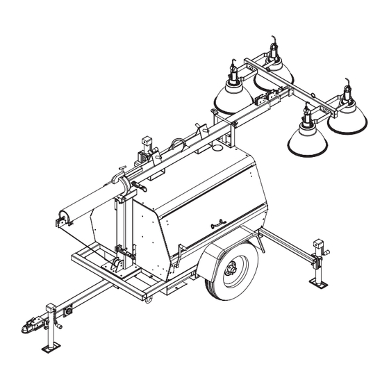
November 2006 SPECIFICATIONS & DIMENSIONS TEREX Amida model AL4000 series light tower provides mobile, trailer mounted floodlighting for nighttime maintenance, construction, mining, and emergency work. It consists of a trailer with a diesel powered 6 kW 60Hz (50 Hz units available) generator, and a 30 foot cable actuated tower with four (4) 1000 watt floodlight fixtures. -
Page 27: Torque Specifications
November 2006 TORQUE SPECIFICATIONS MISCELLANEOUS SPECIFICATIONS The Amida AL4000 light tower is built to NEC standards. FASTENER TORQUE SPECIFICATIONS All fasteners should be torqued to the following specifications in lb-ft (lb-in): SAE FASTENER TORQUE CHART • This chart is to be used as a guide only unless noted elsewhere in this manual • A574 High Strength Grade 5 Grade 8... -
Page 28: Troubleshooting
November 2006 TROUBLESHOOTING The engine and generator are set at the factory. These units are tested and set to 1800 RPM at 60 HZ for proper operation in the field. These units should never require additional adjustments in the field. Adjustments should only be made by a qualified service technician, otherwise the manufacturer’s warranty may become void. - Page 29 November 2006 TROUBLESHOOTING TROUBLE POSSIBLE CAUSE REMEDY 6.Engine runs but produces a a.Crankcase oil level is too high a.Drain oil to its proper level dense smoke b.Low compression b.Have a trained mechanic inspect for broken or seized rings. Inspect valve clearances 7.Engine overheats a.Blocked cooling air intakes a.Inspect the front and rear intakes...
- Page 30 November 2006 TROUBLESHOOTING TROUBLE POSSIBLE CAUSE REMEDY 11.Lamp will not start e.Improper ballast e.The ballast name plate data should agree with the line voltage and lamp used. If not, replace the ballast. f.Lamp has been operating; cool f.Switch off breaker and allow lamp down time insufficient to cool.
- Page 31 November 2006 TROUBLESHOOTING TROUBLE POSSIBLE CAUSE REMEDY 18.Lamp flickers or goes out- c.Defective lamp c.Replace lamp intermittent or cycling d.High spike ballast d.Ballast produces high spike current. Measure with oscilloscope. Replace ballast as required. IF YOU FEEL AN ELECTRIC SHOCK AT ANY TIME WHILE OPERATING THIS UNIT, SHUT IT DOWN IMMEDIATELY! HAVE THE UNIT INSPECTED BY A TRAINED ELECTRICIAN.
- Page 32 November 2006 LIGHT FIXTURE TROUBLESHOOTING TRACEABLE NUMBERED WIRING SYSTEM (Using plug-in ballasts to troubleshoot) When troubleshooting the preceeding problems, minimize down time by following the traceable numbered wiring system, always follow these steps: STEP1: Ensure all ballasts, which are numbered, are plugged into lead wires with corre- sponding numbers.
-
Page 33: Warrranty
After inspecting the defective part(s), and it is determined that warranty is due, we will then, at the discretion of TEREX LIGHT CONSTRUCTION , credit the applicants account or send replacement parts. - Page 34 Rock Hill, S.C. 29732 MANUFACTURER’S LIMITED WARRANTY TEREX LIGHT CONSTRUCTION (“TLC”) warrants to the original purchaser that such equipment, accessories, parts and other products manufactured by TLC will be free from defects in workmanship and material for a period of one (1) year after the date of first delivery or for two thousand (2,000) hours of use, whichever comes first;...
-
Page 35: Serial Number Record
When ordering parts, PLEASE INCLUDE THE MODEL AND SERIAL NUMBER located on the nameplate of the tower. For major repair and service or other information, contact your local Terex dealer or write to: Terex Light Construction P.O. -
Page 36: Model Number Identification
November 2006 MODEL NUMBER IDENTIFICATION AL4000 Light Tower Part No. 833002 Rev A... -
Page 37: Recomended Oil
November 2006 RECOMENDED ENGINE OIL & FUEL KUBOTA D1105 DIESEL ENGINE Engine oil should be MIL-L-2104C or have properties of API classification of CD grades or higher. Change the type of engine oil according to the ambient operating temperature: Above 77°F (25°C) SAE 30 32°F to 77°F (0 to 25°C) SAE 20... -
Page 38: Wire Rope Replacement
When used properly, the wire ropes should give years of trouble-free service, depending on how often the masts are raised and lowered. The rule of thumb at TEREX is that if the tower is raised and lowered an average of once per day, that the cables should be replaced every two years of service. - Page 39 November 2006 WIRE ROPE REPLACEMENT BROKEN CABLE REPLACEMENT PROCEDURE 1. PREPARATION Collapse tower to where mast is retracted, then pivot tower to horizontal position. Remove the tower from the trailer and place it on a work surface such as two saw horses. 2.
- Page 40 November 2006 WIRE ROPE REPLACEMENT Pass the free end of the cable through the sheave slot between the large and middle sections and out of the top of the tower. Pull the cable and the middle section completely out of the large section altogether.
- Page 41 November 2006 WIRE ROPE REPLACEMENT Cable Replacement Diagram Part No. 833002 Rev A AL4000 Light Tower...
-
Page 42: Wire Rope Replacement
November 2006 WIRE ROPE REPLACEMENT Tower Shim Placement AL4000 Light Tower Part No. 833002 Rev A... -
Page 43: Wiring Diagrams
November 2006 Wiring Diagrams Section Part No. 833002 Rev A AL4000 Light Tower... - Page 44 November 2006 Fixture Wiring Diagram AL4000 Light Tower Part No. 833002 Rev A...
- Page 45 November 2006 1000MH Ballast Diagram Part No. 833002 Rev A AL4000 Light Tower...
- Page 46 November 2006 1000HPS Ballast Diagram AL4000 Light Tower Part No. 833002 Rev A...
- Page 47 November 2006 AC Wiring For A Light Tower Diagram Part No. 833002 Rev A AL4000 Light Tower...
- Page 48 November 2006 DC Engine Wiring Diagram AL4000 Light Tower Part No. 833002 Rev A...
- Page 49 November 2006 AC Light Tower Wiring Diagram - Perkins Part No. 833002 Rev A AL4000 Light Tower...
- Page 50 November 2006 Consolidated Coil Cord With Plug End AL4000 Light Tower Part No. 833002 Rev A...
- Page 51 November 2006 Parts Catalog Section Part No. 833002 Rev A AL4000 Light Tower...
-
Page 52: General Information Parts Manual
NOTES and DESIGNATIONS This manual is compiled from information available and current at time of approval for printing. Terex reserves the right to improve its product without notice to follow its policy of constantly striving to manufac- ture a better product. -
Page 53: Parts Ordering Information
When ordering parts for a specific unit, follow the instructions listed below. By doing so, you will be assured of receiving the correct part in the shortest period of time. 1. Send your order to the nearest Terex distributor in your area. 2. Give the light tower model and serial number. -
Page 54: Trailer Frame/Tongue/Outriggers
November 2006 TRAILER FRAME/TONGUE/OUTRIGGERS ITEM # PART # DESCRIPTION QTY. 841430 JACK SIDEWIND LONG 3KLB 840222 JACK SNAP RING 114480 OUTRIGGER 2X2X42 109150 KIT: OUTRIGGER PLUNGER PIN KIT 721051 CAPLUG,TUBE PLUG 2 1/2 834219 HANDLE (ARM)FOR JACK, HAMMERBLOW 834204 HANDLE (ARM)FOR JACK, FULTON 840221 JACK BRACKET SWIVEL 111936... -
Page 55: Fuel Tank
November 2006 FUEL TANK ITEM # PART # DESCRIPTION QTY. 990200 NUT LOCK NYLON INSERT 1/2-13NC GR 2 990210 WASHER FLAT 1/2 742240-1 TANK CAP NO-GAUGE 792750 CLAMP 7/16 TO 25/32 890795 HOSE,FUEL 5/16 ID 898590 HOSE FITTING,PIPE/BARB 891560 HOSE FITTING,PIPE/BARB 890785 HOSE,FUEL 1/8 ID 742220... -
Page 56: Axle Assembly
November 2006 AXLE ASSEMBLY AL4000 Light Tower Part No. 833002 Rev A... - Page 57 November 2006 ITEM # PART # DESCRIPTION QTY. 841050 AXLE 3500LB 38.5 SPRING CENTER 834267 U-BOLT KIT - 3500# 834229 SEAL, HYDRAULIC 834226 INNER BEARING 834220 HUB ASSY HT1000 3500LB 834227 OUTER BEARING 834225 SEAL,GREASE 834250 SPINDLE NUT 834228 GREASE CAP 841060 TIRE &...
-
Page 58: Cabinet Assembly
November 2006 CABINET ASSEMBLY AL4000 Light Tower Part No. 833002 Rev A... - Page 59 November 2006 ITEM # PART # DESCRIPTION QTY. 123490 FENDER WITH SKIRT 188570 CABINET SIDE PANEL ROADSIDE 184150 WINCH HANDLE BUSHING 796432 GAS SPRING SHORT BRACKET WITH BALL 124420 GROUND ROD STORAGE TUBE 188530-2 CABINET FRONT PANEL 176370 LITERATURE RACK 188580 CABINET SIDE PANEL CURBSIDE 930950...
-
Page 60: Cabinet Assembly (Top & Doors)
November 2006 CABINET ASSEMBLY (TOP & DOORS) AL4000 Light Tower Part No. 833002 Rev A... - Page 61 November 2006 ITEM # PART # DESCRIPTION QTY. 116180 REAR TOWER SUPPORT, COMPLETE ASSEMBLY 790540 PIN QUICK1/4X1.75 ZP 720220 BUMPER REAR TOWER SUPPORT 123680 PIN W/RING 3/4X11 124460 REAR TOWER SUPPORT 796610 HINGE PIANO 1.5X51.75 188560 CABINET DOOR PANEL 796432 GAS SPRING SHORT BRACKET WITH BALL 992040 RIVET POP 3/16X.602...
-
Page 62: Cabinet Decals
ITEM # PART # DESCRIPTION QTY. 850091 DECAL: DANGER CRUSH HAZARD 851640 DECAL: TOWER OPERATING INSTRUCTIONS 853296 DECAL: TEREX-AMIDA RED AND BLACK 5X29.5 853312 DECAL: STRIPING RED/BLACK 850155 DECAL: NO.2 DIESEL FUEL ONLY 850107 DECAL-CAUTION,WINCHLOCK SYSTEM 853640 DECAL: "CAUTION",WINCH ROTATION 853291 DECAL: TEREX-AMIDA RED AND BLACK 2.75X16... -
Page 63: Tower Assembly
November 2006 TOWER ASSEMBLY ITEM # PART # DESCRIPTION QTY. 113080 COIL CORD SLEEVE 851545 DECAL: DANGER DO NOT RAISE TOWER IN VICINITY R850475 DECAL: WARNING FORKS 851550 DECAL: LIFT MACHINE HERE Part No. 833002 Rev A AL4000 Light Tower... -
Page 64: 4" Tower Section
November 2006 4” INCH TOWER SECTION ITEM # PART # DESCRIPTION QTY. 124540 4" SECTION 30'TOWER 109516 KIT:LOCK SLIDE PIN W/ SPRING & SHELL includes 3-9 990660 ROLL PIN 1/4 X1-5/8 113362 PIN,LOCK SLIDE,WITH RING includes 10-13 171635 LOCK PIN SHELL 171640 LOCK SPRING SHELL 980340... -
Page 65: 4" Tower Section (Sheave & Shim)
November 2006 4” TOWER SECTION (UPPER SHEAVE & SHIM) ITEM # PART # DESCRIPTION QTY. 994920 COTTER PIN 3/32X3/4 SS 990650 COTTER PIN 1/8X1 SS 188760 SHEAVE 3-1/8 X1 1/4 CABLE 990670 RIVET POP 3/16X1/2 S/S BLIND RIVET 183286 SHIM 5/16X2X3-3/16 995780 CLEVIS PIN STAINLESS STEEL 3/8 X2 992765... -
Page 66: 3" Tower Section
November 2006 3” INCH TOWER SECTION ITEM # PART # DECSCRIPTION QTY. 996230 SCREW,3/8-16NCX7/8 990470 WASHER LOCK 3/8 109065 KIT: CABLE ASSEMBLY LOWER 1/4 CABLE 124550 3 SECTION 30'TOWER 188760 SHEAVE 3-1/8 X1 1/4 CABLE 990650 COTTER PIN 1/8X1 SS 994920 COTTER PIN 3/32X3/4 SS 990670... -
Page 67: 2" Tower Section
November 2006 2” INCH TOWER SECTION ITEM # PART # DESCRIPTION QTY. 124560 2 SECTION 30'TOWER 109070 KIT: CABLE ASSEMBLY UPPER 990470 WASHER LOCK 3/8 996230 SCREW,3/8-16NCX7/8 HHC,GR 8 ZP Part No. 833002 Rev A AL4000 Light Tower... -
Page 68: Tower Crossarm Fixture
November 2006 TOWER CROSSARM FIXTURE ITEM # PART # DESCRIPTION QTY. 113040 CROSSARM 4-LIGHT 191781 STUD,3/4X10NCX4-3/4 990880 WASHER LOCK STAR 3/4 EXT.TOOTH 123080 FIXTURE MOUNTING WING NUT 994460 SCREW,3/8-16NCX4-1/2" 990080 WASHER FLAT 3/8 990170 NUT LOCK NYLON INSERT 3/8-16NC GR 2 ZPN 851760 DECAL: DANGER HIGH VOLTAGE.. -
Page 69: 6" Round Tube
November 2006 6” INCH ROUND TUBE ITEM # PART# DESCRIPTION QTY. 990620 NUT LOCK NYLON INSERT 7/8-14NF HALF JAM 994920 COTTER PIN 3/32 X 3/4 SS 990650 COTTER PIN 1/8 X 1 SS 995190 NUT,LOCK NYLON INSERT 1/2-20NF HALF NUT 990610 BOLT TEE 1/2-20NF 4-1/2 LG 188770... -
Page 70: Tower Base Assembly
November 2006 TOWER BASE ASSEMBLY AL4000 Light Tower Part No. 833002 Rev A... - Page 71 November 2006 ITEM # PART # DESCRIPTION QTY. 124490 TOWER BASE REFER TO WINCH DRAWING ON NEXT PAGE 981450 SCREW,3/8-16NCX1-1/2 990470 WASHER LOCK 3/8 990080 WASHER FLAT 3/8 990140 SCREW 1/4-20NCX2 990150 NUT LOCK NYLON INSERT 1/4-20NC GR 2 ZP 124480 WINCH HANDLE W/TUBE 853670...
-
Page 72: Winch Assembly
November 2006 WINCH LOCK ASSEMBLY AL4000 Light Tower Part No. 833002 Rev A... - Page 73 November 2006 ITEM # PART # DESCRIPTION QTY. 990080 WASHER FLAT 3/8 990470 WASHER LOCK 3/8 981450 SCREW, 3/8-16NC X 1-1/2 HHCS,GR 5 990650 COTTER PIN 1/8 X 1 SS 980480 WASHER, FLAT, C816L, S/S, 1/2 F/W 7/8 OD 124858 ROLLER WEAR BUSHING 740050-1 KIT: WINCH &...
-
Page 74: Engine/Genset Assembly
November 2006 ENGINE/GENSET ASSEMBLY ITEM # PART # DESCRIPTION QTY. 732205PP KUBOTA D1105 ENGINE POWERPACK BUILD EBG2 839190 LOW OIL PRESSURE SWITCH 741140 HIGH TEMPERATURE SWITCH 866125 AIR CLEANER ASSEMBLY 866126 AIR CLEANER BODY 866127 AIR CLEANER ELEMENT 866128 AIR CLEANER COVER 866129 AIR CLEANER VALVE 866050... -
Page 75: Radiator Assembly
November 2006 RADIATOR ASSEMBLY ITEM # PARTS # DESCRIPTION QTY. 866114 RADIATOR 866120 CAP FOR RADIATOR 839109 HOSE, TOP 839110 HOSE, BOTTOM 866113 FAN GUARD 865307 COOLANT RECOVERY TANK 890790 HOSE FUEL 1/4X1/2 200# Part No. 833002 Rev A AL4000 Light Tower... -
Page 76: Radiator Mounting Bracket
November 2006 RADIATOR MOUNTING BRACKET ITEM # PART # DESCRIPTION QTY. 995380 SCREW, 1/2-13NC X 6-1/2 HHC, GRADE 5, ZP 990210 WASHER FLAT 1/2 990415 WASHER, FLAT SNUBBER 740925 VIBRATION MOUNT, 30 DUR 740770 VIBRATION MOUNT 35 LB 124015 ENG.FT/RAD SUPPORT ROADSIDE, D1105/LSA36 (shown) 124016 ENG.FT/RAD SUPPORT CURBSIDE D1105/LSA36 (not shown) 124025... -
Page 77: Generator Mounting Bar
November 2006 GENERATOR MOUNTING BAR ITEM # PART # DESCRIPTION QTY. 836704 NDE BEARING 836705 DIODE KIT (includes 2 diodes) 836706 ROTOR BOLT (8 X 245) 836707 TOP COVER 836708 END CAP 836709 836710 TERMINAL BLOCK 836711 CAPACITOR, 22.5mf, (two per unit required) 996290 SCREW, M10X1.5X90MM HHC, GRADE 8.8, ZP 990415... -
Page 78: Electrical Control Box Assembly
November 2006 ELECTRICAL CONTROL BOX ASSEMBLY AL4000 Light Tower Part No. 833002 Rev A... - Page 79 November 2006 ITEM # PART # DESCRIPTION QTY. 853294 DECAL: AL/RL CONTROL BOX AC "POWER & LIGHT" 683680 BREAKER 2P 30A 240V 186546 CONTROL BOX,FACE PLATE 709133 TERMINAL,RING 683870 BREAKER 1P 15A 277VAC 684640 RECEPTACLE 20A 120V DUPLEX W/GFI 683970 BREAKER MINI 1P 20A 684450 RECEPTACLE 30A 240V...
-
Page 80: Mh/Hps Light Fixture Assembly
November 2006 MH/HPS LIGHT FIXTURE ASSEMBLY AL4000 Light Tower Part No. 833002 Rev A... - Page 81 November 2006 ITEM # PART # DESCRIPTION QTY. 663850 CORD SET MALE 5FT. 3P 709034 TERMINAL STRIP, 2P 833567 CASTING FOR NEW FIXTURE 995970 WASHER LOCK STAR 1/2 991650 WASHER LOCK 1/2 990810 SCREW 1/2-13NCX1-1/2 HHC GR 2 ZP 833566 TRUNION 833573 T-HANDLE...
-
Page 82: Ballast Assembly
November 2006 BALLAST ASSEMBLY ITEM # PART # DESCRIPTION QTY. 114355 BALLAST BOX MH 114895 BALLAST BOX HPS 663860 CONNECTOR,5P,MALE 160030 MH TRANSFORMER AND CAPACITOR 160040 HPS TRANSFORMER AND CAPACITOR 160032 CAPACITOR ONLY 24uF MH 60Hz 160042 CAPACITOR ONLY 24uF HPS 60Hz AL4000 Light Tower Part No. -
Page 83: Coil Cord & Junction Box
November 2006 COIL CORD & JUNCTION BOX ITEM # PART # DESCRIPTION QTY. 685673 PIN, MALE 685671 CONNECTOR 9P,MALE 660287 CORD RETRACT 14/7 663870 CONNECTOR 3P FEMALE 663880 DUST CAP W/CHAIN C48300108 JUNCTION BOX 680190 BOX COVER 2GANG W/GASKET 852800 DECAL: CAUTION TIGHTEN FIXTURE CONNECTOR 680080 GRIP-HUBBLE... -
Page 84: Trailer Hitches
November 2006 TRAILER HITCHES ITEM # PART # DESCRIPTION QTY. 940000 KIT: COMBO HITCH, includes items 2-6 840120 COUPLER, 2", BOLT ON 176336 COMBO HITCH SIDE SPACER 176335 COMBO HITCH SIDE PLATE 840470 BALL, 2" 121572 COMBO HITCH RING, 16" LONG 213770 RING HITCH BOLT-ON, 2-1/2 ID 124450... -
Page 85: Al4000 Options
November 2006 AL4000 OPTIONS ITEM # PARTS # DESCRIPTION QTY. 124310 SPARE TIRE MOUNT 5-LUG WHEEL 188070 CLAMP,SPARE TIRE BRKT,TONGUE MNT. 841060 TIRE & WHEEL MOUNTED P205/75-15 LOAD-B 160530 BATTERY BLANKET THERMO 284-4001 36"LG 684030 LIGHT DOME WITH SWITCH 741690 FUEL LINE HEATER, DIESEL,12V,150W 684640 RECEPTACLE 20A 120V DUPLEX W/GFI... -
Page 86: Al4000 Options
November 2006 AL4000 OPTIONS (CONTINUED) ITEM # PARTS # DESCRIPTION QTY. 174170 BATTERY HOLDOWN ANGLE 14.50 161085 BATTERY, WET, 12V GR24, 700 AMP HEAVY-DUTY L/A 182331 BATTERY HOLD-DOWN ROD,1/4X11-1/4 110040 OUTRIGGER 2X2X30 124412 TRAILER FRAME,41X70, FOR EXTRA OUTRIGGERS 109150 KIT: OUTRIGGER PLUNGER PIN ASSY 840222 JACK SNAP RING 841430...
Need help?
Do you have a question about the AL4000D2 Series and is the answer not in the manual?
Questions and answers