
Summary of Contents for Adrenaline Amusements Spinner Frenzy SF-50-1001
- Page 1 Spinner Frenzy SF-50-1001 Operation & Service Manual Version 1.0 * Read this manual before use...
-
Page 2: General Remark
If you encounter any difficulties or if you need support on how to update and/ or install your Spinner Frenzy Arcade product, we invite you to contact your local distributor or reach us at support@aagames.com or by calling our support line +1-450-824-1671 Adrenaline Amusements Team Adrenaline Amusements 1150 Levis, Suite 302 Terrebonne, Qc... -
Page 3: Table Of Contents
Spinner Frenzy Manual V1.0 Table of Contents Contents General Remark ....................2 Table of Contents ....................3 Chapter 01 - Preface ................... 5 Precaution for Game Operation ....................5 Safety ............................6 Environmental Conditions ......................6 Chapter 02 - Game Features ................7 Chapter 03 –... - Page 4 Spinner Frenzy Manual V1.0 Cabinet Parts ..........................38 Computer & Electronics ......................40 Header & LEDs ........................... 41 Spinner RGB PCB ........................42 Cabling ............................43 Wiring Harness .......................... 44 Chapter 08 – Diagrams & Schematics ..............45 I/0 Board ADR-04-1001 ......................45 I/O Board - Spinner Sensors Wiring ..................
-
Page 5: Chapter 01 - Preface
Do not block cooling vents. Precaution for Game Operation Adrenaline Amusements Inc. assumes no liability for injuries incurred while playing our games. Operators should be aware that certain health and physical conditions may make people susceptible to injury when playing video games. -
Page 6: Safety
Spinner Frenzy Manual V1.0 Chapter 01 - Preface Safety To avoid electrical shock, unplug the cabinet before performing installation or service procedures. If a power cord is damaged, it must be replaced by the equivalent power cord available from your distributor. Adrenaline Amusement Inc. -
Page 7: Chapter 02 - Game Features
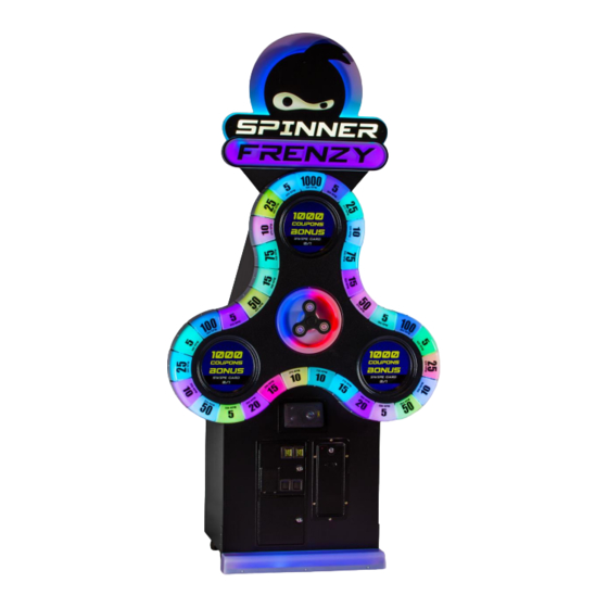
Spinner Frenzy Manual V1.0 Chapter 02 – Game Features Chapter 02 - Game Features Spinner Frenzy is an addictive game! It requires precision, not strength! How to Play Spin the Spinner Wheel to exactly 500 RPM and win the bonus! ... -
Page 8: Chapter 03 - Unit Features
Spinner Frenzy Manual V1.0 Chapter 03 – Unit Features Chapter 03 – Unit Features Hardware Features 4 Monitors (1 Hidden into Side Service Door) Amazing Interactive RGB LEDs animations. 100% Skill Game, challenge your friends! Cabinet Facts Cabinet Dimensions Depth = 33.21”... -
Page 9: Voltage
Spinner Frenzy Manual V1.0 Chapter 03 – Unit Features Voltage Voltage Operating 110V AC 2.5 AMP 220V AC 1.25 AMP P a g e... -
Page 10: Chapter 04 - Unit Installation
Spinner Frenzy Manual V1.0 Chapter 04 – Unit Installation Chapter 04 – Unit Installation Assembling your Spinner Frenzy Unit **You need to be 2 persons to assemble the unit** 1. Carefully remove the Cabinet from the shipping container, giving you enough space. Move the cabinet to the desired location. - Page 11 Spinner Frenzy Manual V1.0 Chapter 04 – Unit Installation Install the header using the 4 provided lock bolts. Connect the cables for the RGB LEDs and the White LEDs coming from the top of the cabinet to the Header. 11 | P a g e...
-
Page 12: Chapter 05 - Operator Menu
Spinner Frenzy Manual V1.0 Chapter 05 – Operator Menu Chapter 05 – Operator Menu Operator Menu Access the Operator Menu by pressing the Operator button located inside the drawer on the I/O board directly. Operator: Open the Operator Menu Up/Down: Scroll Up/Down & Increase/ Decrease Value Select Button: Select/Deselect 12 | P a g e... - Page 13 Spinner Frenzy Manual V1.0 Chapter 05 – Operator Menu Operator Menu Values What It Does Credits Per Game 1-20 Adjusts the number of credits required to play. “0” sets the unit in free play mode. Adjusts the in-game audio volume. “0” will mute the Game Audio Volume 0-20 game.
-
Page 14: Ticket Payouts Structures
Spinner Frenzy Manual V1.0 Chapter 05 – Operator Menu Ticket Payouts Structures If you choose a different ticket payouts structure than the one originally installed, refer to the on-screen images to install the good values cover at their good positions. The extra value covers are located in the bottom cabinet. - Page 15 Spinner Frenzy Manual V1.0 Chapter 05 – Operator Menu Use Payout 01 if you want to use Coin Value 0.25$ and use Bonus Value Cover 100. 15 | P a g e...
- Page 16 Spinner Frenzy Manual V1.0 Chapter 05 – Operator Menu Use Payout 02 if you want to use Coin Value 0.75$ and use Bonus Value Cover 500. 16 | P a g e...
- Page 17 Spinner Frenzy Manual V1.0 Chapter 05 – Operator Menu Use Payout 03 if you want to use Coin Value 1.00$ and use Bonus Value Cover 500 for a Low Payout. 17 | P a g e...
- Page 18 Spinner Frenzy Manual V1.0 Chapter 05 – Operator Menu Use Payout 04 if you want to use Coin Value 1.00$ and use Bonus Value Cover 1000 for a Medium Payout. 18 | P a g e...
- Page 19 Spinner Frenzy Manual V1.0 Chapter 05 – Operator Menu Use Payout 05 if you want to use Coin Value 1.00$ and use Bonus Value Cover 1000 for a High Payout. 19 | P a g e...
- Page 20 Spinner Frenzy Manual V1.0 Chapter 05 – Operator Menu Use Payout 06 if you want to use Coin Value 1.50$ and use Bonus Value Cover 1000. 20 | P a g e...
- Page 21 Spinner Frenzy Manual V1.0 Chapter 05 – Operator Menu Use Payout 07 if you want to use Coin Value 2.00$ and use Bonus Value Cover 1000. 21 | P a g e...
-
Page 22: Chapter 06 - Service & Repair
Spinner Frenzy Manual V1.0 Chapter 06 – Service & repair Chapter 06 – Service & Repair Computer Connections Description USB Port to RGB LED Controller USB Port to I/O Board Audio Jack to Amplifier Power Barrel Connector USB License Dongle USB Restore Flash Drive VGA to VGA Splitter Adapter 22 |... -
Page 23: Troubleshooting
Spinner Frenzy Manual V1.0 Chapter 06 – Service & repair Troubleshooting * NOTE: When requesting a warranty replacement you will be asked to give the unit’s serial number from the back of the unit. Video Troubleshooting There could be loose or faulty connections between the monitor and the VGA Splitter. -
Page 24: Monitor Replacement
Spinner Frenzy Manual V1.0 Chapter 06 – Service & repair Monitor Replacement This section covers: Monitor replacement, Monitor power supply replacement, VGA cables replacement, Spinner shaft replacement, Spinner Sensors replacement, Solenoid controller replacement, Solenoid (Brake) replacement. Unlock the side service door. ... - Page 25 Spinner Frenzy Manual V1.0 Chapter 06 – Service & repair Remove the Spinner and his shaft by pulling it from the cabinet. Unscrew and remove the Values cover all around the Large Spinner. 25 | P a g e...
- Page 26 Spinner Frenzy Manual V1.0 Chapter 06 – Service & repair Disconnect the 2 RGB connectors harness. 26 | P a g e...
- Page 27 Spinner Frenzy Manual V1.0 Chapter 06 – Service & repair Unscrew the Large Black Spinner by removing all the screws. Be careful so it doesn’t drop on the floor. 27 | P a g e...
- Page 28 Spinner Frenzy Manual V1.0 Chapter 06 – Service & repair Gently pull the large black Spinner. Disconnect the Solenoid Controller 4-Pins connector. Disconnect the RGB 3-pins wiring connector and the 10-pins connector. Then remove the large spinner completely aside. 28 | P a g e...
- Page 29 Spinner Frenzy Manual V1.0 Chapter 06 – Service & repair If you look from the back of the unit you can find the 3 screws that hold in place the 2 bottom monitors. 29 | P a g e...
- Page 30 Spinner Frenzy Manual V1.0 Chapter 06 – Service & repair If you need to replace a VGA cable you need to do the previous steps. If you need to replace a monitor and/or monitor power supply you need to do the previous steps. ...
- Page 31 Spinner Frenzy Manual V1.0 Chapter 06 – Service & repair To replace the upper monitor, remove the header first. Somebody needs to hold the monitor to avoid it to fall; Remove the screws holding the monitor from outside the service door. ...
- Page 32 Spinner Frenzy Manual V1.0 Chapter 06 – Service & repair To replace the Solenoid (Brake) Remove the 4 bolts from the front plate. Remove the 6 screws holding the front wooden plate. 32 | P a g e...
- Page 33 Spinner Frenzy Manual V1.0 Chapter 06 – Service & repair Pull away the wooden plate with the solenoid installed on it. Replace the Solenoid and re-install the wooden plate. 33 | P a g e...
-
Page 34: Front Kickboard Assembly Rgb Led Replacement
Spinner Frenzy Manual V1.0 Chapter 06 – Service & repair Front Kickboard Assembly RGB LED replacement Remove the 4 screws holding the metal footrest from the cabinet 34 | P a g e... - Page 35 Spinner Frenzy Manual V1.0 Chapter 06 – Service & repair Remove the 3 screws on the front and 3 on the back to get access to the LEDs PCB. 35 | P a g e...
- Page 36 Spinner Frenzy Manual V1.0 Chapter 06 – Service & repair When replacing the PCB verify the connections so that the arrows points always in the same direction. 36 | P a g e...
-
Page 37: Wireless Internet Configuration
If not, here’s how to configure your wireless network with your own existing Wi-Fi network. -Start the unit. -There will be Adrenaline Amusements wallpaper with a 150 seconds delay before the attract mode shows up. It gives enough time for a wireless network to connect. -
Page 38: Chapter 07 - Parts
Spinner Frenzy Manual V1.0 Chapter 07 – Parts Chapter 07 - Parts Cabinet Parts 38 | P a g e... - Page 39 Spinner Frenzy Manual V1.0 Chapter 07 – Parts Part Description Part # Monitor 17” VGA with Tempered Glass SF-10-0001 Cover LED Type 1 SF-09-0001-#-RPM Cover LED Type 2 SF-09-0002-#-RPM Spinner Assembly SF-02-1001 Spinner Thermoformed Frame SF-05-0004 Front Center Ring Cover SF-05-0005 Speakers 4”...
-
Page 40: Computer & Electronics
Spinner Frenzy Manual V1.0 Chapter 07 – Parts Computer & Electronics Part Description Part Number VGA Splitter 1 to 4 INV-VS-814H Audio Amplifier 2X15W INV-14-0005 Computer Intel NUC ADR-11-1016 RGB LED Controller INV-14-1030 Power Supply 130W +5V/15A +12V/4A ADR-80-0210-00 Power Supply +5V/60A SF-14-0010 Outlet Power Bar IEC C13 5-Ports INV-05-1242... -
Page 41: Header & Leds
Spinner Frenzy Manual V1.0 Chapter 07 – Parts Header & LEDs Part Description Part Number Thermoformed Ninja Header SF-09-0001 “Frenzy” RGB LEDs Strip SF-14-0007 “Ninja” RGB LEDs Strip SF-14-0008 “Spinner” & “Eyes” White LEDs Strip SF-14-0009 41 | P a g e... -
Page 42: Spinner Rgb Pcb
Spinner Frenzy Manual V1.0 Chapter 07 – Parts Spinner RGB PCB Part Description Part Number “Concave” PCB SF-14-0001 “Convex Left” PCB SF-14-0002 “Convex Right” PCB SF-14-0003 Jumper Board SF-14-0004 Jumper Board “Power” SF-14-0005 Center Ring RGB LEDs Strip SF-14-0006 42 | P a g e... -
Page 43: Cabling
Spinner Frenzy Manual V1.0 Chapter 07 – Parts Cabling Part Description Part Number 1’ USB “AB” cable INV-USB-AB1-01BK Power Splitter Cable IEC-C14 to 2X IEC-C13, INV-PW-200B-03 18AWG, 3’ Splitter 1-Female To 2-Males 2.1mm for TF-05-1223 Amplifier & VGA Splitter Power Adapter C14 to 5-15R INV-PW-AD023 (Computer PSU Adapter) Power Cable IEC-C13 to IEC-C14, 14AWG, 3’... -
Page 44: Wiring Harness
Spinner Frenzy Manual V1.0 Chapter 07 – Parts Wiring Harness Part Description Part Number Harness from I/O to Solenoid Controller SF-03-0001 (Inside Large Spinner) Harness from I/O to Solenoid Controller SF-03-0002 (Inside Cabinet) Harness from RGB LED Controller to SF-03-0003 Spinner Values LEDs Harness from RGB LED Controller to SF-03-0004... -
Page 45: Chapter 08 - Diagrams & Schematics
Spinner Frenzy Manual V1.0 Chapter 08 – Diagrams & Schematics Chapter 08 – Diagrams & Schematics I/0 Board ADR-04-1001 No Use No Use Power Aux Player Ticket 1. (Red) +12V 1. (Red) +12V 2. (Black) GND 2. (White) OUT 3. (White/Black) +12V 3. - Page 46 Spinner Frenzy Manual V1.0 Chapter 08 – Diagrams & Schematics No Use No Use No Use 5V/12V Input DC USB To Computer Coin Door Player No Use No Use 1. (White) +12V 2. (Black) GND 3. (Red) IN1 4. (Yellow) IN2 5.
- Page 47 Spinner Frenzy Manual V1.0 Chapter 08 – Diagrams & Schematics Speakers Wiring Colors 47 | P a g e...
-
Page 48: I/O Board - Spinner Sensors Wiring
Spinner Frenzy Manual V1.0 Chapter 08 – Diagrams & Schematics I/O Board - Spinner Sensors Wiring 48 | P a g e... -
Page 49: I/O Board - Coins & Ticket Wiring
Spinner Frenzy Manual V1.0 Chapter 08 – Diagrams & Schematics I/O Board - Coins & Ticket Wiring 49 | P a g e... -
Page 50: Power Distribution Schematics
Spinner Frenzy Manual V1.0 Chapter 08 – Diagrams & Schematics Power Distribution Schematics 50 | P a g e... - Page 51 Spinner Frenzy Manual V1.0 Chapter 08 – Diagrams & Schematics 51 | P a g e...
-
Page 52: Rgb Led Wiring
Spinner Frenzy Manual V1.0 Chapter 08 – Diagrams & Schematics RGB LED Wiring LED Wiring (Global View) 52 | P a g e... - Page 53 Spinner Frenzy Manual V1.0 Chapter 08 – Diagrams & Schematics RGB LED Wiring (Channel 1 View) Refer to Page 39 for PCB RGB parts. 53 | P a g e...
- Page 54 Spinner Frenzy Manual V1.0 Chapter 08 – Diagrams & Schematics RGB LED Wiring (Channel 2 View) 54 | P a g e...
- Page 55 Spinner Frenzy Manual V1.0 Chapter 08 – Diagrams & Schematics RGB LED Wiring (Channel 3 View) 55 | P a g e...
- Page 56 Spinner Frenzy Manual V1.0 Chapter 08 – Diagrams & Schematics RGB LED Wiring (Channel 4 View) 56 | P a g e...
-
Page 57: Chapter 09 - Software Recovery
Spinner Frenzy Manual V1.0 Chapter 09 – Software Recovery Chapter 09 – Software Recovery If your unit software needs to be restored please follow those instructions. Connect a USB keyboard to the motherboard. Connect the provided USB Recovery flash disk is in a Black USB port. Power on the unit and press F10 on the keyboard to display the boot menu. -
Page 58: Chapter 10 - Card Reader
Spinner Frenzy Manual V1.0 Chapter 10 – Card Reader Chapter 10 – Card Reader Configure your Operator settings as seen on page 13. 58 | P a g e... -
Page 59: Embed System
Chapter 10 – Card Reader Embed System If you are using an Embed system, you need to connect your harnesses to Adrenaline Amusements I/O board & harnesses. You should refer to the Embed instructions manual for wiring pin-out but here’s... - Page 60 Spinner Frenzy Manual V1.0 Chapter 10 – Card Reader The typical Embed settings are Standard except: -Ticket Mech Type: Dumb DC -Drive Polarity: Positive -Notch Polarity: Negative -Game ticket notch width = 10 -Game ticket notch spacing = 15 -Game Drive Threshold = 1.5V -Notch Pulse = 60ms -Ticket Space = 240ms -Drive Debounce = 40ms...
-
Page 61: Limited Warranty Policies
Improper servicing or abuse will VOID existing warranties. All warranty request needs to be validate with our technical support department. After the 1 year warranty, Adrenaline Amusements offers repairs & sales services options. Please contact the technical support department for information.
Need help?
Do you have a question about the Spinner Frenzy SF-50-1001 and is the answer not in the manual?
Questions and answers