Table of Contents
Advertisement
Read Carefully !
1
This manual contains safety information that if ignored
can endanger life or result in serious injury. They are
indicated by this icon.
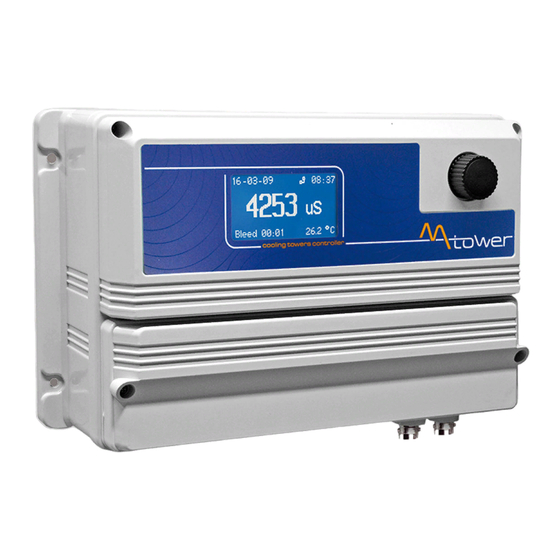
Keep the instrument protected from sun and water.
Avoid water splashes.
OPERATING INSTRUCTIONS F O R
" MAX5" INSTRUMENT
Configuration and screenshots may be different and not including
some functions. A maximum of 5 channels can be set.
DOWNLOAD ERMES COMMUNICATION SOFTWARE
www.ermes-server.com
ENGLISH Version
R36-01-18
Advertisement
Table of Contents

Related Manuals for Emec MAX5


Summary of Contents for Emec MAX5
- Page 1 Keep the instrument protected from sun and water. Avoid water splashes. OPERATING INSTRUCTIONS F O R “ MAX5” INSTRUMENT Configuration and screenshots may be different and not including some functions. A maximum of 5 channels can be set. DOWNLOAD ERMES COMMUNICATION SOFTWARE www.ermes-server.com...
-
Page 2: General Safety Guidelines
NORME CE EC RULES(STANDARD EC) NORMAS DE LA CE ⎬ Direttiva Bassa Tensione Low Voltage Directive 2014/35/UE Directiva de baja tensión ⎬ Direttiva EMC Compatibilità Elettromagnetica 2014/30/UE EMC electromagnetic compatibility directive EMC directiva de compatibilidad electromagnética GENERAL SAFETY GUIDELINES Danger! In emergencies the instrument should be switched off immediately! Disconnect the power cable from the power supply! When installing always observe local regulations! - Page 3 The wheel. Located in the upper right side of MAX5 there is a wheel that must be used to control the instrument. Wheel can be rotated in both directions to scroll over the menus and / or pressed to confirm highlighted selection / value.
-
Page 4: Mainboard Connections
Mainboard Connections. Unplug instrument from main power supply then perform connections to probes and / or selected outputs by following the above picture. For easy understanding board as been divided into two parts: Power connections and I/O connections. For EClx series probes, NTU connections and ETHERNET version, see APPENDIX A at page 30. Block numbers are related only to its own part of the board. - Page 5 (Ref. A Appendix - Inductive Conductivity module) ECDIND probe: 54(+) ; 55(GND) Standby signal input: *This is “FLOW1” for “MAX5 PH CL PH CL double flow” model only **This is “TEMP2” for “MAX5 PH CL PH CL double flow” model only...
-
Page 6: Main Screen
Main screen. From main screen all instrument fucntions can be reached by rotating the wheel and highlighting the selected option. Options available are located in the low right corner of the screen. Connection Status LAN CONNECTION OK - ERMES CONNECTION OK LAN CABLE DISCONNECTED LAN CABLE CONNECTED - ERMES NOT AVAILABLE fig. - Page 7 Passcode. From main screen rotate wheel until to highlight then press wheel. Note: This is a passcode protected area. For this reason every time this menu is reached, the instrument will ask for a passcode as shown. fig. 2 If this is a “first time visit” the default passcode is “0000” (both Administrator and User). Just press four times the wheel.
- Page 8 Setpoint. From setup menu (fig.3) rotate wheel to highlight “Setpoint” then press wheel. Again rotate wheel until to reach desired measure between pH - Cl - mV - NTU - Temperature. Customized version includes: potentiostat (mg/l Cl ) and Fluorine (F) fig.
- Page 9 Da and Db WORKING MODES. ON/OFF Mode. On/Off mode set the instrument to operate using two set values that enable or disable the related setpoint output. Parameters to set for this mode are: ON: Activate RL and LEV on moving towards the unit value (for example: pH) OFF: Disable RL and LEV on moving towards the unit value (for example: pH) assign “input”...
-
Page 10: Pwm Mode
If reading value decreases to 8.00 then the output will be OFF for 20 seconds, ON for 80 seconds. fig. 5 Notes: for values within 1% and 5% MAX5 will assume 5% as usable value. for values within 95% and 99% MAX5 will assume 95% as usable value. - Page 11 PID Mode. A proportional–integral–derivative controller (PID controller) is a generic control loop feedback mechanism. PID controller attempts to correct the error between a measured process variable and a desired setpoint by calculating and then outputting a corrective action that can adjust the process accordingly. The PID controller calculation (algorithm) involves three separate parameters;...
- Page 12 Pa and Pb. Using PxA and / or PxB is possible to control the status of “Proportional pump outputs” based on some parameters. Refer to “I/O connections” blocks at page 5 to locate these outputs over the mainboard. Once that PxA or PxB function is enabled (move wheel over “disable”...
- Page 13 Using mA is possible to control the status of “mA outputs” based on some parameters. Refer to “I/O connections” blocks at page 5 to locate these outputs over the mainboard. Once that mA1 function is enabled (move wheel over “disable” , press, rotate to “enable”, press again to exit) then main parameters are OUTmA, LEV, STOP and pH - mA.
- Page 14 Aa and Ab Using Aa and / or Ab is possible to set a visual alarm with delay for values ≥ or ≤ than set value. Once that Aa or Ab function is enabled (move wheel over “disable” , press, rotate to “enable”, press again to exit) then main parameters are ALARM and DELAY.
- Page 15 Using AR is possible to set a visual alarm if probe’s reading value continues to be the same for a set time. Time can be set between 1minute and 9hours and 59minutes. fig. 10 MSG. when flagged an SMS or EMAIL alarm message will be sent to destination edited in GSM menu.
- Page 16 Calibration. From setup menu (fig.3) rotate wheel to highlight “Calibration” then press wheel. Again rotate wheel until to reach desired calibration measure pH - Cl2 - mV - NTU and Temperature. fig. 11 pH Calibration. pH calibration procedure involves two calibration points and it requires two buffer solutions. Default buffer solutions are pH 4.00 and pH 7.00.
- Page 17 and press wheel to proceed to next step. Note: buffer solution value may change if environment temperature it’s different than 20°C. Read solution’s label for more information. According to this occurrence “pH Default” must be changed. Comp Auto / Select Temp. Once into submenu, to enable automatic temperature compensation, move wheel on “DISABLE”...
- Page 18 Cl Calibration. Cl calibration procedure involves probe’s selection, Zero and 2nd Point calibration. fig. 14 This procedure assumes that instrument is correctly configured and a working Chlorine probe connected and installed on system. Measurement must be performed using plant water. Otherwise unattended results may occurr.
- Page 19 Calib Zero. Once into “Calibration Cl” menu move on “Calib Zero” then press wheel to enter into calibration mode. For a correct system calibration proceed as follows. - install an “activated carbon filter” prior to probe’s holder. - let system water flow into probe holder for about 30 minutes. - press wheel (cursor must be on “OK”).
- Page 20 mV Calibration. ORP calibration procedure involves one calibration point and it requires one buffer solution. Default buffer solution is 650mV. fig. 15 This procedure assumes that instrument is correctly configured and a working ORP probe connected. Otherwise unattended results may occurr. Once into “Calibration mV”...
- Page 21 Range (NTU). Once into “Calibration NTU” menu move wheel on “Range” to see probe’s scale. “ETORBH” probe’s reading range can be set within: 9,999NTU - 99,99NTU - 999,9NTU - 9999NTU. For reset calibration procedure select “Redo calibration”. SONDA “ETORBH”...
- Page 22 Temp Calibration. Temperature calibration needs an external thermometer to match probe’s reading value. fig. 17 This procedure assumes that instrument is correctly configured and a working temperature probe connected. Otherwise unattended results may occurr. Once into “Calibration Temp” menu move wheel on “Calibration” then press wheel to enter system temperature obtained from a thermometer.
- Page 23 Once satisfied press wheel, move cursor on “OK” and press wheel again. See page 35 for proper scale settings. Also available TDS conductivity with 0-9999 scale. 2) Turn off MAX5. Remove cover and locate CD module jumper settings as shown on page 35. Set jumpers as required. Put cover back to MAX5.
- Page 24 4) Move cursor on “Comp Auto” then press wheel. Rotate wheel to Enable or disable automatic temperature compensation. Enabling this option will override “Select Temp” setup then move cursor on “ESC” or “OK” and press wheel to confirm. fig. 41 5) Move cursor on “Temp Coeff”...
- Page 25 31 Choose one or both two related outputs (not previously assigned , chlorine output exception) that will be enabled during set time. Out1, Out2, ect. are referred to MAX5 channel. This is the activity starting time. Toff This is the activity ending time.
- Page 26 TIMER 2 (to 5) Timer2 is usually used for activities such as a “anti algae treatment”. Once the function is enabled (move wheel on disable, click and then rotate) there are 6 main parameters to set. Timer starts at a specified time of the year and can be repeated every xx days. fig.
- Page 27 Options. From setup menu (fig.3) rotate wheel to highlight “Options” then press wheel. Main options are: fig. A fig. B fig. C TAU : It determines how quickly reading on display follows the reading of the probe. It can be changed between 0 and 30.
-
Page 28: Clock Setup
FLOW DETECT Choose the flow sensor input, set to “Direct” activates the standard flow sensor (“SEPR” proxy sensor). Set to “Reverse” the digital logic of the sensor is inverted. Set to “Disable” the flow sensor is not enabled. MSG. If flagged an SMS / EMAIL alarm message will be sent to recipients added in communication menu. OUT mA. -
Page 29: Eeprom Reset
PROBE CLEAN Once into submenu, to enable probe clean, move wheel on “DISABLE” , press it and change option to “ENABLE”. fig. 23 CYCLE: time until next probe clean. HH (hours) and MM (minutes). CYCLE T: probe cleaning duration. MM (minutes) and SS (seconds). RESTORE T: idle time after probe clenaing procedure. -
Page 30: Gsm Modem
GSM MODEM MAX5 may remotely send SMS alarm messages using its own modem (where available). Options can be configured as follows: SMS1 / SMS2 /SMS3: Using the wheel enter a mobile phone that will receive alert SMS messages if something wrong occurrs. - Page 31 TCP/IP MAX5 may be remotely operated using a standard ethernet connection (on demand). A static or dynamic IP address and a CAT5 ethernet cable is required. According to your network capacity connection speed is 10/100Mbps.To obtain a valid IP address and subnet mask contact your net administrator. Enter parameters and move cursor on “SEND” to store parameters then move on “OK”...
- Page 32 - Make certain the antenna location is not shielded by metal objects or near sources of electrical ‘noise’. - Make certain the distance from the antenna and the “MAX5” or its accessories is of a minimum of 1meter (3.28ft). - Do not route the cable where it could be pinched in doors, windows etc.
-
Page 33: Alarm Setup
ALARM SETUP When an alarm condition is displayed and general alarm output is possible to choose between two working modes. Continuos: alarm condition never stops until “ESC” is pressed. Timered: alarm condition ends after set time. fig. 30 LOG SETUP Log setup stores instrument activities when an alarm (flow, level, general) occurs or after a set time fig. - Page 34 Manual. Outputs may be activated manually for testing purposes. fig. 33 “Manual Relay” will activate “setpoints outputs” (see page 4). Exiting from manual mode will revert selected output to its original condition. fig. 34 “Manual Pulse” will activate “Proportional pump outputs” (see page 5) with selectable pulses from 0 to 150 for each ouptut.
- Page 35 “Manual mA” will activate “mA outputs” (see page 5) with selectable pulses from 0 to 20mA for each ouptut. Exiting from manual mode will revert selected output to its original condition. fig. 36 “Manual Level” will show “Tank level inputs” (see page 5). fig.
- Page 36 Module suitable for: Module suitable for: Module suitable for: ECL1 ECL4 Temperature probe SCLxx probes ECL2 ECL5 Temp1 ( “MAX5 PH CL PH CL double flow” model only) ECL3 ECL6 ECL8 ECL7 Connect as follows: Connect probe ECL9 as follows: Block n.1 : Red wire...
- Page 37 CONDUCTIVITY modules MAX5 PROBE TYPE JUMPERS SETTINGS Probe Platinum Graphite Inox Scale 0 - 300.0 uS ECDHL/01 ECDI/01 OPEN CLOSED CLOSED 0 - 3000 uS ECDHL/1 ECDC/1 ECDI/1 OPEN CLOSED OPEN 0 - 30.00 mS ECDHL/1 ECDC/1 CLOSED OPEN OPEN 0 - 30.00 mS...
- Page 38 TURBIDITY module (ETORBH / ETORB40 probe) Connect turbidity probe as follow: mod. ETORBH mod. ETORB40* 1 Green 1 Blue 2 Yellow 2 Brown 3 Black 3 Black 4 White 4 White 5 Brown 5 Green If ETORBH pobe is supplied with extra cable connect wires as follows: 1 Green 2 Yellow 3 Black+ White...
-
Page 39: Ph & Temperature Compensation
MDPS potentiostat probe series module Located under mainboard cover there are two connectors that can be used to install probe modules. Modules come pre-installed upon request and may appear different as shown (different configurations). Identify installed modules to correctly connect probes. Block n. - Page 40 INDUCTIVE CONDUCTIVITY module (ECDIND probe) 8 WIRES CABLE: 4 PROBE WIRES 4 PT100 WIRES Connect 4 probe wires to MDIND module as follows: Block n.1 : blue Block n.2 : black Block n.3 : grey When using two probes the scale settings must be the same for both! Block n.4 : red 1 2 3 4...
- Page 41 Appendix B - Installation draw...
- Page 42 Appendix C - Network logical installation scheme PC with “ERMES Software” PC with “ERMES Software” ROUTER WITH DSL MODEM SWITCH MAX5 with ETHERNET CONNECTION...
- Page 43 Appendix D - “LOG USB” Module Located under mainboard cover there is a four pins connector that can be used to install “USB data log module” or “SMS module”. Modules come pre-installed upon request and may appear different as shown (different configurations).
- Page 44 Appendix E - EOLUM Probe Setup and calibration To correctly use the dissolved oxygen (fluorescence membrane) probe perform calibration as described. At first start-up, sensor calibration is required in order to the measuring system to be able to generate accurate measuring values.
-
Page 45: Appendix F - Modbus Setup
Appendix F - MODBUS Setup Modbus is a serial communications protocol originally published by Modicon (now Schneider Electric) in 1979 for use with its programmable logic controllers (PLCs). Simple and robust, it has since become a de facto standard communication protocol, and it is now a commonly available means of connecting industrial electronic devices. From main menu select COMMUNICATION then MODBUS to access the options. -
Page 46: Appendix G - Setpoint Temperature
Appendix G - SETPOINT Temperature Set values to enable (ON) or disable (OFF) the temperature realy output. The instrument will proceed to the ON/ OFF working mode. Example: set ON at 30 °C and OFF at 25 ° C The output will be active for values lower than 30 ° C and it will switch off for values greater than 30 ° C , then it’ll reactivate for values lower than 25 °... - Page 47 Appendix H - Water salinity for CD module For “%” version this is NaCl based on conductivity. See graphic below for comparison and relationship between concentration of Solutions and Conductivity (at 18°C).
- Page 48 Appendix I - Fluorine probe module & calibration In the upper part of the motherboard there are two connectors for the installation of the probe modules. On request, these modules are installed by the manufacturer. For the form of fluoride probe simply connect the probe’s BNC connector.
- Page 49 Appendix L - Chlorine Index / Chlorine S/N For proper SCLxx probe installation channel assignment is required. Within “OPTIONS” menu, select “Chlorine Index” and assign a free channel to the probe. To check probe’s serial number see “Chlorine S/N”. This index is related to phisical slot installation on mainboard.
- Page 50 Appendix - WIFI Connection Within Communication Menu choose “WIFI” to bring wireless sub-menu.To manually enter the WiFi Network highlight and click on first line to the right side of the menu and choose cryptography type (WPA, WEP or OPEN). Otherwise move cursor below to choose within an existing network.
- Page 51 Index. Introduction......... page 3 ........ The wheel page 3 Mainboard connections..... page 4 ....Power Connections page 4 page 5 ...... I/O Connections Main Screen........page 6 ........ Passcode page 7 ........Setup page 7 Setpoint..........page 8 Da & Db ........
- Page 52 Index. Options..........page 27 ......... page 27 Delay (outputs & sms) ..... page 27 FM Counter......... page 27 ......Flow Detect page 28 Clock Setup ......page 28 page 29 ......Probe Clean page 29 ......EEprom Reset RS485 page 29 ........
- Page 56 When dismantling this instrument please separate material types and send them according to local recycling disposal requirements. We appreciate your efforts in supporting your local Recycle Environmental Program. Working together we’ll form an active union to assure the world’s invaluable resources are conserved.
Need help?
Do you have a question about the MAX5 and is the answer not in the manual?
Questions and answers