Advertisement
Available languages
Available languages
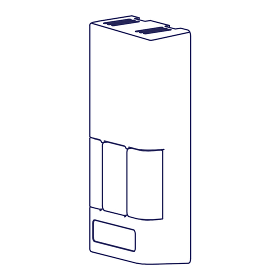
The controls are to be surface mounted onto a wall. Only one master
control should be installed to a ventilation system (the face plate on
this illustration may not be exactly the same as yours).
1.
Separate the face plate from the back plate by firmly
pulling apart (Figure A). Be careful not to damage face
plate contact pins.
2.
For mounting the control without a Decora plate, break off
top and bottom tabs and refer to Figure C for mounting.
3.
Place the back plate of the control in the desired location
on the wall and pencil mark the top and bottom screw
holes (Figure B or C).
4.
Remove the back plate and mark the center hole for the
wires in the middle of the screw holes. Refer to Figure B or
C for placement.
5.
Cut in a 3/4 in by 1 in oval hole in the wall to allow for the
wire opening and drill (two) 1/8 in holes for the screws and
wall anchors (Figure B or C).
6.
Pull 3 wire 20 gauge (min.) 100 ft length (max.), through
the opening in the wall.
7.
Connect red, green, and yellow to the wiring terminals
located on the back plate (Figure B or C).
8.
Attach the back plate to the wall using the 2 supplied
screws and anchors.
9.
Attach the face plate to the back plate (Figure A). Note: Be
careful to correctly align the face plate to avoid damaging
the face plate contact pins.
10.
Connect the 3 wire 20 gauge (min.) 100 ft length (max.) to
the terminal block located on ventilator (Figure D).
Turning on the Control
Press and release the ON/OFF button
illuminate.
Setting the Ventilation Speed
Press and release the Fan button
LO and HI indicator lights are off, the fan is OFF but will turn ON if required by the Dehumidistat or remote Timer (if installed).
Humidity Control
Your unit will reduce indoor humidity when outdoor humidity levels are lower than indoor humidity levels. This feature is only
effective when the outdoor temperature is below 59˚F (15˚C).
Setting the Dehumidistat
Press and release the Dehumidistat button
Dehumidistat light will either flash or be on continuous.
A flashing light indicates the humidity level is higher than the setting and the unit is operating on high speed ventilation. A
continuous light indicates the humidity level is lower than the setting. Refer to the unit's Home Owner's manual for instructions on
how the Dehumidistat works.
The Dehumidistat will override the current speed setting to HIGH speed.
The Dehumidistat function can be turned OFF by pressing the
Note - Only 1 Dehumidistat should be installed in a system.
Control Installation and Operation Instructions
. The light above will
to select LOW or HIGH fan speed. The corresponding "Indicator Light" will illuminate. If both
until the Dehumidistat Light is at the desired setting. After a few seconds the
Pay special attention not to damage
the contact pins when removing and
attaching the face plate (Figure A).
Back Plate
Figure A
Face Plate
Keep top / bottom
vent openings clear
Alternate Wall Mount
Break off tab
1/8 in hole for
screw and
anchor
1 in x 3/4 in
0.75"
oval hole
for wire
opening
1"
Wiring
Terminals
Break off tab
button until no Dehumidistat light is on.
ATTENTION
1/8 in hole for
screw and
anchor
1 in x 3/4 in
oval hole
for wire
opening
1"
Wiring
Terminals
1/8 in hole
for screw and
anchor
Figure C
Red #3
Yellow #4
Wire hole
centered
Green #5
between
screw
holes
1/8 in
hole for
screw and
Figure D
anchor
1.625"
0.75"
1.625"
Figure B
TI-BC02
07_10_15
Advertisement
Table of Contents

Subscribe to Our Youtube Channel
Related Manuals for Airia 99-BC04

Summary of Contents for Airia 99-BC04
- Page 1 Control Installation and Operation Instructions The controls are to be surface mounted onto a wall. Only one master ATTENTION control should be installed to a ventilation system (the face plate on this illustration may not be exactly the same as yours). Pay special attention not to damage Separate the face plate from the back plate by firmly the contact pins when removing and...
- Page 2 Installation et fonctionnement de la commande Les commandes doivent être montées en surface sur un mur. ATTENTION Il ne doit y avoir qu’une seule commande principale pour un système de ventilation. (La plaque avant illustrée ici pourrait différer légèrement de la vôtre.) Veillez à...
- Page 3 Caution: Changes or modifications not expressly approved Airia Brands Inc. could void the user’s authority to operate the equipment. This device complies with part 15 of the FCC Rules. Operation is subject to the following two conditions: (1) This device may not cause harmful interference, and (2) this device must accept any interference received, including interference that may cause undesired operation.
Need help?
Do you have a question about the 99-BC04 and is the answer not in the manual?
Questions and answers