
Summary of Contents for Construction Robotics MULE 135
- Page 1 MULE 135 Owner’s Manual Please read the Owner’s Manual carefully and make sure you understand the instructions before using the machine.
- Page 2 Page Intentionally Left Blank...
- Page 3 Should there be any discrepancies discovered throughout any published documentation issued by Construction Robotics or its authorized affiliates, the following order of precedence shall prevail: 1. Written documents issued by the Construction Robotics Engineering Department 2.
- Page 4 Page Intentionally Left Blank...
-
Page 5: Table Of Contents
Table of Contents SYSTEM OPERATION A INTRODUCTION 1 Controller Buttons ..........28 1 Thank You ..............1 RUN STOP ............. 28 2 System Overview ............1 Manual/Calibrate Up/Down ......28 3 Product Registration and Warranty ......1 Speed ............. 28 Warranty Period .......... - Page 6 Page Intentionally Left Blank...
-
Page 7: Thank You
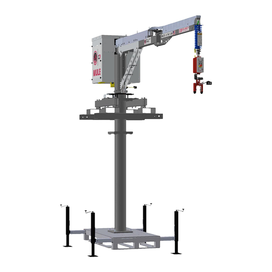
SECTION A – INTRODUCTION A INTRODUCTION 1 Thank You Thank you for choosing a MULE 135. This Owner’s Manual is a valuable document. Make sure it is always on hand at the job site. 2 System Overview MULE is a work area tool used to assist in the lifting and placement of units and material up to 135lb over an 11’... -
Page 8: Safety Overview
SECTION A – INTRODUCTION 5 Safety Overview 1. All operators should read the Operators Manual before operating the Unit 2. Check the wire rope for improper seating, twisting, kinking, wear, or defects before operating. 3. The installation and operation of MULE is subject to hazards that can be avoided only by using extreme care and common sense. -
Page 9: Owner's Manual Use
Be sure the load attachment is properly seated in the saddle of the gripper or hook. Balance load properly before handling. Avoid gripper tip loading. 6 Owner’s Manual Use This manual is for use with the following Construction Robotics model numbers, for any other models contact CR for documentation: •... -
Page 10: B System Summary
SECTION B – SYSTEM SUMMARY B SYSTEM SUMMARY 1 Meet MULE MULE is a smart material handling tool designed for construction that does the heavy lifting for you. Features and benefits: • MULE makes any material weightless up to 135 pounds •... -
Page 11: Weights
Figure B-4 3 Optional MULE Accessories Below is the list of currently available MULE accessories. Construction Robotics is constantly in development of new products, our most current list is available on our website. Custom accessories can be developed upon request, contact Construction Robotics for more information. -
Page 12: Fork Tubes Adapter Plate
SECTION B – SYSTEM SUMMARY Fork Tubes Adapter Plate CMU Gripper 1” - 2 1/4” W/Button Mount Allows Mast Sections to be directly mounted to the Fork Tubes. Without special engineering approval, The CMU Gripper 1” - 2 1/4” W/Button Mount is this is only for use with Strap-over style MCWP the first of many grippers available for MULE. -
Page 13: System Dimensions
SECTION B – SYSTEM SUMMARY 4 System Dimensions Inches (Centimeters) Page 7... - Page 14 SECTION B – SYSTEM SUMMARY Inches (Centimeters) Page 8...
-
Page 15: Safety Features
SECTION B – SYSTEM SUMMARY Inches (Centimeters) 5 Safety Features Rotation Lock When power is removed from MULE, a pin is engaged to lock the rotation of the Primary Arm. This is primarily used in 2 situations; when building/dismantling MULE and moving MULE. When MULE is being transported between sites, there is a pin that can be inserted to prevent the lock from coming disengaged. -
Page 16: Basic Requirements
SECTION B – SYSTEM SUMMARY Overload Protection The software running MULE is constantly monitoring the load on the Wire Rope. If the capacity of 135lb is exceeded the software will only allow for the controller to be lowered at a slow speed. This feature prevents heavy loads from being lifted and possibly damaging the unit or risking a tip-over. -
Page 17: C System Setup
SECTION C – SYSTEM SETUP C SYSTEM SETUP 1 Owner’s Manual Limitations This manual is for use with the following Construction Robotics part numbers, for any other parts contact CR for documentation: • CR003340 – MULE 135 (which includes sub-assemblies CR003341, CR003342 and CR003344) •... -
Page 18: Setup Process
SECTION C – SYSTEM SETUP 3 Setup Process Base Distance from Wall The distance MULE sits from the wall face determines how many lineal feet of wall can be worked in a single setup. In some cases, MULE must be set further back than desired due to site obstacles. No problems will be encountered if the area in Figure C-1 is clear. -
Page 19: Outrigger Position
SECTION C – SYSTEM SETUP Cribbing may be needed under each jack foot to Outrigger Position increase the bearing surface capacity. Before assembling MULE the outriggers within the Ground Base have to be extended and locked into When using cribbing, ensure that the position. -
Page 20: Handle Installation
SECTION C – SYSTEM SETUP Strain Relief – Push the rubber tabs attached to the Wheel Set Assembly – Optional black coil cord on to the studs. The tab closest to Accessory the connector should be installed on the back set of For MULE to be assembled to the Wheel Set, the studs. -
Page 21: Fork Tube Disassembly
SECTION C – SYSTEM SETUP Once the Fork Tubes have been removed MULE can Fork Tube Disassembly be lifted into place using the rigging points or the On some setups, it can be beneficial to remove the Fork Tubes can be lowered down around the mast. Fork Tubes for either capacity or head height reasons. -
Page 22: Mounted To Wheel Set
SECTION C – SYSTEM SETUP CR Mast Free-Standing When utilizing MULE in a single location with CR Mast it can Free-Stand up to 22 ft of mast. Wall Ties When site conditions require MULE to be built taller than Free Standing will allow, the Mast can be tied into existing structure. -
Page 23: Fork Tubes
SECTION C – SYSTEM SETUP During the move of the Wheel Set, the following requirements must be followed: • The surface must be swept to clear any obstacles • The path must be inspected for overhead obstacles • The jacks must be no more than ½” off the floor •... -
Page 24: Assembling The Mast And Installing Mule
SECTION C – SYSTEM SETUP CR Mast When working with the CR Mast in a tied configuration, additional components are required. Wall ties can only attach at the interface of 2 mast sections. At that interface the standard 3” bolts are switched with fully threaded 4”... - Page 25 SECTION C – SYSTEM SETUP Assuming more than 1 section of mast is being used lift MULE up with the Fork Tubes. Bolt a single mast section to the bottom of MULE using the same hardware and procedure as used for the base. All of the bolts run from the bottom up and the head is captured to only require 1 tool.
- Page 26 SECTION C – SYSTEM SETUP The base adapter is a 2 piece assembly that gets bolted onto the Ground Base using the rectangular hole pattern in the center of the pallet. Be sure the bolts that interface with the HM mast are installed prior to attaching the assembly to the Ground Base.
-
Page 27: Raising Mule Height (Adding Mast Sections)
SECTION C – SYSTEM SETUP 7 Raising MULE Height (Adding Mast Sections) Once MULE is assembled and needs to be raised to change the work zone, Mast sections need to be added. Before unplugging MULE, raise the Controller as high as possible Ensure that MULE is unplugged and the Primary Arm rotation lock is engaged to prevent movement;... -
Page 28: Moving Mule On A Jobsite
SECTION C – SYSTEM SETUP 8 Moving MULE on a Jobsite As work is completed MULE will need to be relocated to keep producing. Before moving MULE, make sure that the wind conditions are within the operational requirement of 30 mph. Ensure that MULE is unplugged and the Primary Arm rotation lock is engaged to prevent movement;... -
Page 29: Wheel Set
SECTION C – SYSTEM SETUP Wheel Set If your setup is built to the Flat and Smooth Surfaces exception within Section C4.2 (Page 16) be sure that the area of travel complies with ALL requirements and the specific procedures are followed. The Wheel Set is ideal for sites that have solid, flat and consistent System Required Bearing... -
Page 30: Mule Dismantling And Packing For Transport
SECTION C – SYSTEM SETUP 9 MULE Dismantling and Packing for Transport When installation/dismantling or rigging requires the certified installer to exceed safe working heights allowable per OSHA or site specific regulations the use of approved fall protection is required. When MULE is finished working on a site it can be packed into a convenient package for transport. -
Page 31: D System Setup On Mast Climbing Platform
SECTION D – SYSTEM SETUP ON MAST CLIMBING PLATFORM D SYSTEM SETUP ON MAST CLIMBING PLATFORM 1 Introduction As Mast Climbing Work Platforms’ (MCWP) are so critical in construction, CR has made special mounting solutions to optimize the valuable deck space and decrease overall system weight. At this time, CR has 2 different styles of dedicated MCWP mount. -
Page 32: Strap-Over Deck Mount
SECTION D – SYSTEM SETUP ON MAST CLIMBING PLATFORM 3 Strap-over Deck Mount Overview The Strap-over deck mount allows for MULE to be mounted in nearly any position on the scaffold with no permanent modifications required. Utilizing this mounting kit MULE can be installed quickly to the scaffold. Check with CR for the appropriate hardware set for your scaffold. -
Page 33: On Existing Hydro Mobile Mast Tower
SECTION D – SYSTEM SETUP ON MAST CLIMBING PLATFORM 4 On Existing Hydro Mobile Mast Tower In some cases it may be desired to mount MULE directly to a HM mast that is also supporting the scaffold deck. Hydro Mobile has approved this special use of their product when being used with MULE. When using either the M or P-Series units MULE can be attached directly to the top of the mast that is supporting the scaffold. -
Page 34: Esystem Operation
SECTION E – SYSTEM OPERATION E SYSTEM OPERATION 1 Controller Buttons RUN STOP The RUN STOP button disables all functionality on the Controller and Actuator. When pressed the screen will show “E-STOP ENGAGED” Manual/Calibrate Up/Down Typically used as the calibration for the load weight in RUN MODE FLOAT. -
Page 35: Set
SECTION E – SYSTEM OPERATION The SET button changes the load from feeling weightless to having some weight when the Controller screen shows “RUN MODE FLOAT”. Pressing SET again changes the load back to feeling weightless. When placing a load on a soft material (ie setting a block in a mortar bed) this feature is very advantageous. -
Page 36: Primary Arm Rotation Lock
SECTION E – SYSTEM OPERATION 4 Primary Arm Rotation Lock The Primary Arm is equipped with a locking mechanism to prevent the arm from swinging when MULE is not powered. The lock is driven by the pneumatic system and can be manually operated if desired. Sometimes it is necessary to rotate the arm while not powered. -
Page 37: Ftransport And Storage
SECTION F – TRANSPORT AND STORAGE F TRANSPORT AND STORAGE 1 Shipping Position MULE can be shipped attached only to the Fork Tubes or assembled with masts and the Ground Base as it was initially received. In either case, it is important to support both of the arms in both the up and down directions. -
Page 38: Gsettings And Troubleshooting
SECTION G – SETTINGS AND TROUBLESHOOTING G SETTINGS AND TROUBLESHOOTING 1 Key Access Areas Arm Access Panel Powerpack Service Panel 2 Friction Brake Adjustment The friction brakes control how fast the arms move and how quickly they start and stop. Looser friction brakes allow the arm to move easier but also allow for more unintended movement. -
Page 39: Secondary Arm
SECTION G – SETTINGS AND TROUBLESHOOTING With the panel removed, a hole near the rigging eye is exposed. Insert the extension into the silver piece below and attach the breaker bar or ratchet. Little adjustment is needed to change the feel of the arm, adjust the nut no more than 1/8 of a turn at a time. -
Page 40: Virtual Limits
SECTION G – SETTINGS AND TROUBLESHOOTING 3 Virtual Limits If work is being performed repeatedly in the same height range, limits can be set to prevent the Controller from travelling up or down further than intended. To set and adjust Virtual Limits see the Controller Menu section (G4 on page 34). 4 Controller Menu The current software version is V1.00, for any other versions refer to information specific for that version. -
Page 41: Software Flowchart
SECTION G – SETTINGS AND TROUBLESHOOTING Software Flowchart Page 35... - Page 42 SECTION G – SETTINGS AND TROUBLESHOOTING Page 36...
- Page 43 SECTION G – SETTINGS AND TROUBLESHOOTING Page 37...
-
Page 44: Pneumatic System
SECTION G – SETTINGS AND TROUBLESHOOTING 5 Pneumatic System Air Compressor MULE contains an integrated Air Compressor to power the gripper and rotation lock. This compressor’s integrated regulator is set to 80 psi. Pneumatic Connection Diagram Page 38... -
Page 45: Electrical Information
SECTION G – SETTINGS AND TROUBLESHOOTING 6 Electrical Information Transformer Adjustments MULE requires a specific voltage range in order to function. In the event that your voltage supply does not match the listed requirements, there is an adjustable transformer on board to compensate for this. If the Powerpack Service Panel is removed, you will notice a digital readout on the electrical enclosure. -
Page 46: Electrical Connection Diagram
SECTION G – SETTINGS AND TROUBLESHOOTING Electrical Connection Diagram Power Control Page 40... -
Page 47: Primary Arm Rotation Lock
SECTION G – SETTINGS AND TROUBLESHOOTING 7 Primary Arm Rotation Lock The Primary Arm Rotation Lock should be disengaged when MULE is powered on. If it fails to release, several typical settings should be checked. Check that the handle can release the lock. If it does not release, the lock pin is likely still engaged from transport. -
Page 48: Troubleshooting
SECTION G – SETTINGS AND TROUBLESHOOTING 9 Troubleshooting Common Issues Failure Possible Solution Controller screen shows • Briefly press one of the MANUAL CALIBRATE buttons until the Controller “EXCESSIVE PAUSE” moves Primary arm rotation lock • Ensure MULE is plugged in will not disengage •... -
Page 49: Error Codes
SECTION G – SETTINGS AND TROUBLESHOOTING Wire Rope continues to • Test slack detection system (Section H2.4 on page 45) pay out after load has been placed Wire Rope will not move • Test slack detection system (Section H2.4 on page 45) down when gripper is unloaded without excessive force... -
Page 50: Hpreventative Maintenance And Basic Service
SECTION H – PREVENTATIVE MAINTENANCE AND BASIC SERVICE H PREVENTATIVE MAINTENANCE AND BASIC SERVICE 1 Maintenance Summary Daily • Pre-shift inspection on Wire Rope • Pre-shift inspection on MULE Power Cord • Drain Air Compressor Tanks • Inspect for structural damage and loose parts Weekly •... -
Page 51: Lubrication
SECTION H – PREVENTATIVE MAINTENANCE AND BASIC SERVICE Lubrication MULE’s Wire Rope comes pre-lubricated from the Factory. As MULE is used and the Wire Rope flexes the lubricant will need to be replenished. CR recommends that the Wire Rope is lubricated with Prelube 6 which is available through CR. OSHA prohibits the use of any Wire Rope lubricants that hinder inspection. - Page 52 SECTION H – PREVENTATIVE MAINTENANCE AND BASIC SERVICE Feed the Wire Rope through the coil cord so that the Wire Rope has a direct path to the ground. Attach a 10 lb load to the Wire Rope directly. Using the MANUAL/CALIBRATE DN button attempt to move the load down, if the load does not move the slack spring is too tight and must be adjusted (see If 10 pound weight was unable to drive down) Figure H-3 Attach a 5 lb load to the Wire Rope directly.
-
Page 53: Replacement
SECTION H – PREVENTATIVE MAINTENANCE AND BASIC SERVICE Replacement Warning: Wire Rope replacement is to be performed by qualified maintenance personnel only. Tools: With your right hand keep tension on the Wire Rope through the Arm Access Panel (use a rag •... - Page 54 SECTION H – PREVENTATIVE MAINTENANCE AND BASIC SERVICE Using the 3mm Allen key, 6mm Allen key, 8mm wrench and 17mm wrench remove the 2 bolts holding the pulley block at the end of the arm. Using the 5mm Allen key, remove 2 bolts from plastic drum cover, slide cover out.
- Page 55 SECTION H – PREVENTATIVE MAINTENANCE AND BASIC SERVICE Installing New Wire Rope Take care to keep new rope clean and orderly during installation. Avoid twisting or kinking Wire Rope. Slide the stop sleeve end of the Wire Rope through the arm to the actuator. Bend the Wire Rope approximately 3”...
-
Page 56: Pneumatic System
SECTION H – PREVENTATIVE MAINTENANCE AND BASIC SERVICE 3 Pneumatic System Any service to the air system should be performed with the compressor drained and the valve locked in the open position to prevent accidental pressurization. Air Compressor To drain the air compressor, unplug MULE and open the ball valve at the bottom of the Powerpack. Filter The compress filter should be cleaned monthly to increase longevity and performance. -
Page 57: Rollers On Arm
SECTION H – PREVENTATIVE MAINTENANCE AND BASIC SERVICE 6 Rollers on Arm If the filter has become plugged with 2 sets of rollers should be inspected to ensure contaminates or physically damaged the filter that they are still functional. If any structural should be replaced. - Page 58 Powerpack Primary Arm Power Cord Secondary Arm Fork Tubes Controller Gripper Handle Mast Ground Base Part Weight (lb) MULE 135 (weight w/out fork tubes) Fork Tubes 5' Mast 2 1/2' Mast Ground Base Total Weight as Shown 2455 Page 52...
- Page 59 Page Intentionally Left Blank...
- Page 60 795 Canning Parkway Victor, NY 14564 (585)-742-2004 info@robotics.build www.robotics.build © 2018 Construction Robotics, LLC All Rights Reserved Patent Pending...
Need help?
Do you have a question about the MULE 135 and is the answer not in the manual?
Questions and answers