
Subscribe to Our Youtube Channel
Summary of Contents for BEP TS1
- Page 1 Ultrasonic Tank Sender Installation and Operating Instructions For TS1 Firmware v3.8 Page 1 INST-TS1-V13 18/11/10...
-
Page 2: Table Of Contents
FREQUENTLY ASKED QUESTIONS ............11 Important TS1 Installation Issues 1. The sender must not be mounted closer than 150mm from the centre of the sender to sides of the tank, baffles or other intrusions. 2. Only use on tanks greater than 200mm in depth. -
Page 3: Features
Liquids that have higher viscosities than water (e.g. oil) may not propagate liquid ripples that create a strong return signal. This will also have a tank depth de-rating effect. Don’t use on tanks shallower than 200mm in depth as angular reflections will reduce accuracy. Page 3 INST-TS1-V13 18/11/10... -
Page 4: Dimensions
3. Dimensions 95.35 [3 3/4"] ACOUSTIC PROTRUSION 95.35 [3 3/4"] Page 4 INST-TS1-V13 18/11/10... -
Page 5: Mounting And Installation
2 full turns. Maximum torque for the mounting screws is 0.5 Newton meter. Note: Drawing is not to scale. Please use the tank gasket as a template and make sure the tank hole is 42mm. Page 5 INST-TS1-V13 18/11/10... -
Page 6: Case
It is recommended the sender is mounted in the middle of the tank, this is particularly important on low or no baffled tanks that are mounted in moving vehicles or vessels. This allows the TS1 to average waves of fluid to the correct level when the depth is varying due to wave slop. - Page 7 Case 4 Acoustic protrusion must not touch the tank frame! Case 5 TS1 must be mounted so it can see the bottom of the tank if the liquid is to be measured to the bottom. Page 7 INST-TS1-V13 18/11/10...
-
Page 8: Case
Case 7 Do not fit the TS1 with a tube. Case 8 Ensure bolts and mounting holes are aligned properly to keep plastic body isolated acoustically from tank. -
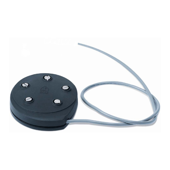
Page 9: Wiring
5. Wiring Power must be removed before TS1 is connected to the system. Ensure wiring is correct or else damage may occur rendering the device inoperable. Page 9 INST-TS1-V13 18/11/10... -
Page 10: Programming And Setup
Computer with USB Port (BEP P/N TS1) (BEP P/N TS1-PK) Please visit the BEP website for the programming software. 7. Problem Solving Water Tanks After long periods of no use, condensation will build up on the roof of the water tank and the sender face. -
Page 11: Frequently Asked Questions
Q: Is the TS1 ignition protected? A: The TS1 is ignition protected and approved. It is fully potted. Q: On power up, the analogue gauge goes full scale then back to empty. After 5 seconds it shows the correct level. - Page 12 BEP MARINE 55 Paul Matthews Road, Albany, Auckland 0632 New Zealand PO Box 101739 NSMC Phone (+649)4157261 Fax. (+649)4159327 www.bepmarine.com E-mail: enquiries@bepmarine.com Please visit our website for the latest International Distributor List Page 12 INST-TS1-V13 18/11/10...
Need help?
Do you have a question about the TS1 and is the answer not in the manual?
Questions and answers