Table of Contents
Advertisement
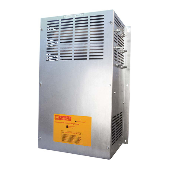
PowerOhm Installation Manual
for "PK" Series
Braking Modules
IMPORTANT: These instructions should be read thoroughly before installation.
All warnings and precautions should be observed for both personal safety and
for proper equipment performance and longevity.
Failure to follow these
instructions could result in equipment failure and/or serious injury to
personnel. Braking modules contain lethal voltages when connected to the
inverter. It is very important to remove power to the inverter before installing
or servicing this unit. Always allow adequate time (approximately 5 minutes)
after removing power before touching any components. The POWER ON LED
must be completely out and the resistor elements cool before servicing the unit
Advertisement
Table of Contents

Summary of Contents for Powerohm Resistors PK series
- Page 1 PowerOhm Installation Manual for “PK” Series Braking Modules IMPORTANT: These instructions should be read thoroughly before installation. All warnings and precautions should be observed for both personal safety and for proper equipment performance and longevity. Failure to follow these instructions could result in equipment failure and/or serious injury to personnel.
- Page 2 Table of Contents • Page 2: Table of Contents for Manual HCPMAN0013_R1 (2015-03-31) • Page 3: Product Overview and Inspection • Page 4: Environmental Conditions and Electrical Ratings • Page 5: Equipment Installation • Page 6: Dimensions and Weight for PKx005 and PKx010 •...
-
Page 3: Product Overview
Product Overview AC variable frequency drives are commonly used with various types of motors to form reliable variable speed drive systems. Problems with these drive systems can occur when an application requires a deceleration rate faster than what can be managed by the drive alone, or when motor speeds exceed the synchronous speed set by the output frequency of the drive (which is called an overhauling load condition). -
Page 4: Environmental Conditions
Environmental Conditions The PowerOhm PK Series Braking Module should be installed in an environment protected from moisture and excessive dust. Dust buildup can reduce the electrical insulation characteristics of the unit and moisture can cause arching or shorting. Air must be free of combustible gases and corrosive vapors. -
Page 5: Equipment Installation
Equipment Installation The PowerOhm PK series Braking Module should be installed on a low vibration surface that is non-flammable. Check for physical damage and for loose wires or plugs after installation. Attention: Installation and removal of this equipment should be done by qualified personnel only. -
Page 6: Dimensions And Weight
Dimensions and Weight The PowerOhm PK series Braking Modules shown below in Figure 2a and Figure 2b includes the dimensions of both units FIGURE 2a: Braking Module Dimensions for Part Numbers PKA005, PKA010, PKB005, PKB010, PKC005 and PKC010 Weight: The weight is approximately 14 lbs. - Page 7 FIGURE 2b: Braking Module Dimensions for Part Numbers PKB050 & PKC050. Weight: The weight is approximately 45 lbs. a brand of ICD, Inc.
-
Page 8: Wiring Recommendations
Wiring Recommendations It is recommended that the AC drive manual and braking module instructions and any other pertinent documentation be thoroughly reviewed before proceeding. Note that control and power wiring should be separated to avoid electrical noise and interference problems. The wiring between the drive and braking module should not exceed 15 feet. -
Page 9: Wire Sizing
Wire Sizing Reference Table 2 for suggested minimum wire sizes only. Keep in mind the duty cycle rating greatly affects the minimum wire size needed. TABLE 2: Wire Sizing for Power Interconnections Motor HP at 10% Duty Cycle WIRE SIZE 240VAC 480VAC 600VAC... -
Page 10: Power Connections
Power Connections Wire Sizing The PowerOhm PK series Braking Module features a total of 2 power connections and an earth ground Terminal location and size is dependent on the current capacity of the model. See reference tables 3a,and 3b for a description of each terminal’s function, torque, type of connection and wire size. - Page 11 TABLE 3b: Description of Power Connections for PKx050 Maximum Terminal Terminal Connection Tool Maximum Torque Designation Description Type Required Wire Size (lb-in) DC - DC Bus Negative 5/16” ring lug #2 Phillips 4 awg DC + DC Bus Positive 5/16” ring lug #2 Phillips 4 awg Power Earth...
-
Page 12: Control Connections
Control Connections The PowerOhm PK series Braking Module features a 10-position terminal block for all signal and control wiring. All terminations on the block can accept bare wire or fork lugs for a #6 screw. Reference Table 4 for a description of each terminal. -
Page 13: Module Setup
Module Setup The PowerOhm PK series Braking Module has several jumper settings that are accessible on the main circuit board. The front cover has to be removed to change the jumper settings. Warning: Do not make jumper changes while power is applied! Change as required only after power is removed and the green power indicator is off! Use insulated tools when changing jumper positions. - Page 14 FIGURE 4b: Control Board Jumper Positions CAUTION: Do not make jumper changes while power is applied! Change as required only when power is removed and the green power indicator is off! Use insulated tools when changing jumper positions. Brake Enable Jumper: JP6 selects between internal enable or external enable modes Internal (Automatic): When the JP6 jumper is in the downward position, the Brake is Enabled automatically whenever system DC Bus voltage is applied.
- Page 15 Line Voltage Level Jumpers: The voltage ID box in fig 4a indicates the voltage class, which determines the DC threshold level for each jumper position. PK series braking modules are calibrated to the DC voltages shown in the JP4 column in table 7, with JP4 ON. Moving the jumper to another position changes the DC turn on thresholds as shown in table 7.
-
Page 16: System Integration
System Integration FIGURE 5: Drive DC BUS Power Connections Internal/External Chopper: In the example above, the internal and external chopper connections are shown. Both should never be used at the same time. An external chopper is needed when a drives internal chopper cannot support the desired duty cycle, or when the drive has no internal chopper transistor. - Page 17 FIGURE 6: Power Connections for a Single Braking Module Master - Slave Jumper Settings: In the example above, the braking module is set as the Master (JP7 is the downward position). Wiring Notes: All DC power wiring between the drive and braking module should be twisted (if possible) and run separate from all control wiring.
- Page 18 FIGURE 7: Power Connections for Multiple Braking Modules Master - Slave Jumper Settings: In the example above, the top braking module is set as the Master (JP7 is the downward position) and the lower module is in Slave Mode (JP7 is in the upward position). •...
- Page 19 FIGURE 8: Control Connections for Multiple Braking Modules Master - Slave Jumper Settings: In the example above, the left braking module is set as the Master (JP7 is the downward position) and the right module is in Slave Mode (JP7 is in the upward position). •...
- Page 20 Start Up PRELIMINARY: • Ensure the DC bus connections are proper polarity. • Make sure that braking module voltage rating is equivalent to the drive and that all voltage selection jumpers are in the proper positions. • Ensure the drives internal braking is disabled. •...
- Page 21 DUTY CYCLE: While under full load increase the duty cycle while monitoring the DC bus level and module resistors. If the resistors are glowing at the end of each braking cycle the duty cycle should be decreased, or a higher rated resistor should be used. (Although the resistors can take extreme temperature they will last longer if they are not stressed to the point of glowing) FAULT: With the brake module sized correctly and the proper decel time and duty cycle...
-
Page 22: Troubleshooting
Troubleshooting NORMAL LED INDICATORS The PowerOhm PK Series Braking Module has three LED indicators that allow the user to verify the following: POWER ON: An illuminated green LED indicates that DC bus voltage is applied to the DC- and DC+ power connections. - Page 23 ABNORMAL SYMPTOMS • Before removing equipment covers or making any changes in jumper positions or adjustments, power down equipment and wait for DC bus to drop to safe levels. Always use an insulated screwdriver or insulated pliers when making jumper changes or adjustments •...
- Page 24 BRAKING LED FLICKERS • During light duty braking or at the end of a braking cycle it is normal for the LED to flicker some • If the LED flickers when the Drive is idle there may be excessive noise on the DC bus from other equipment, a higher than expected AC line level, or high harmonics on the incoming voltage •...
- Page 25 FAULT LED IS ON • Check unit for heatsink or resistor overheating and allow time to cool • Check for proper sizing of brake module as overheating indicates the module is running beyond its capacity a. Reduce the duty cycle or increase the decel time b.
- Page 26 Notes ________________________________________________________________________________________ ________________________________________________________________________________________ ________________________________________________________________________________________ ________________________________________________________________________________________ ________________________________________________________________________________________ ________________________________________________________________________________________ ________________________________________________________________________________________ ________________________________________________________________________________________ ________________________________________________________________________________________ ________________________________________________________________________________________ ________________________________________________________________________________________ ________________________________________________________________________________________ ________________________________________________________________________________________ ________________________________________________________________________________________ ________________________________________________________________________________________ ________________________________________________________________________________________ ________________________________________________________________________________________ ________________________________________________________________________________________ a brand of ICD, Inc.
- Page 27 Notes ________________________________________________________________________________________ ________________________________________________________________________________________ ________________________________________________________________________________________ ________________________________________________________________________________________ ________________________________________________________________________________________ ________________________________________________________________________________________ ________________________________________________________________________________________ ________________________________________________________________________________________ ________________________________________________________________________________________ ________________________________________________________________________________________ ________________________________________________________________________________________ ________________________________________________________________________________________ ________________________________________________________________________________________ ________________________________________________________________________________________ ________________________________________________________________________________________ ________________________________________________________________________________________ ________________________________________________________________________________________ ________________________________________________________________________________________ a brand of ICD, Inc.
- Page 28 HCPMAN0013_R1 (2015-03-31) a brand of ICD, Inc.
Need help?
Do you have a question about the PK series and is the answer not in the manual?
Questions and answers