Advertisement
34280-TE
8-digit LED Frequency Counter Module
Model PLJ-8LED-C
User Manual V 1.0
May 2014
Appendix with test details and schematics and additional notes in the
main text of this manual were added in August 2016 by ZL2PD.
Information including Links and Code (Software) Supplied or Referenced in this Document is
supplied by MPJA inc. as a service to our customers and accuracy or usefulness is not guaranteed
nor is it an Endorsement of any particular part, supplier or manufacturer. Use of information
and suitability for any application is at users own discretion and user assumes all risk.
All rights are retained by the Owners/Author(s)
PLJ-8LED Frequency Counter
User Operating Manual
1
Advertisement

Summary of Contents for Sanjian Studio PLJ-8LED-C
- Page 1 34280-TE 8-digit LED Frequency Counter Module Model PLJ-8LED-C User Manual V 1.0 May 2014 Appendix with test details and schematics and additional notes in the main text of this manual were added in August 2016 by ZL2PD. Information including Links and Code (Software) Supplied or Referenced in this Document is supplied by MPJA inc.
-
Page 2: Table Of Contents
Appendix : Testing and Modifications ....................12 OVERVIEW The PLJ-8LED-C module is a cost-effective 8-digit frequency counter and display module primarily to display the operating frequency in a transceiver and other equipment. It may also be used for conventional frequency measurement. The module offers compact, reliable high performance with clear display at low cost. -
Page 3: Technical Specifications
TECHNICAL SPECIFICATIONS 1. GATE TIME 0.01 sec 0.10 sec 1.0 sec 2. CHANNEL MEASUREMENT PERFORMANCE (CHANNEL LEVEL HIGH IMPEDANCE) Low channel Measuring range: 0.1 MHz - 60 MHz Accuracy: ± 100Hz (0.01 sec gate time) ± 10Hz (0.1 sec gate time) ±... - Page 4 3. IF SETTINGS Independent double-IF design allows the IF settings to be adjusted in minimum increments of 100 Hz. Intermediate frequency range: 0 - 99.9999 MHz Offset: Plus or minus IF mode can be configured 4. FREQUENCY REFERENCE 13.000MHz temperature compensated voltage controlled crystal oscillator (VC-TCXO) in 5032 package ...
-
Page 5: Operation And Use
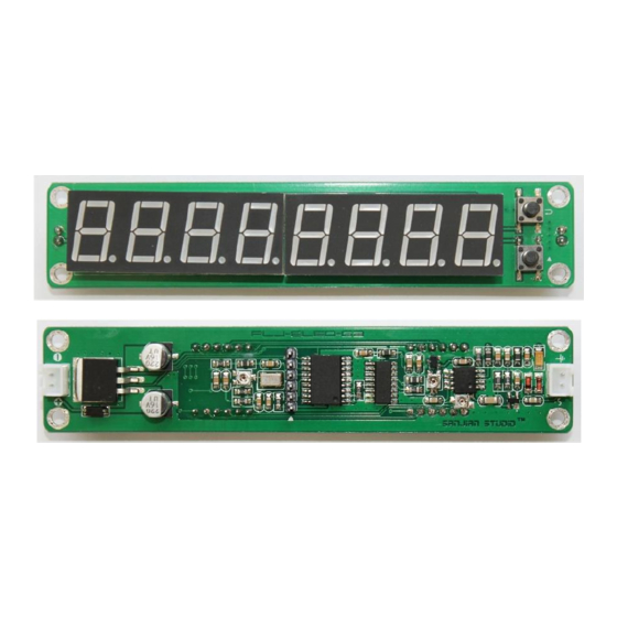
OPERATION AND USE 1. MODULE ARRANGEMENT Front view of module DC In TCXO cal Program Input sensitivity (H/L) RF In Rear view of module Note: This diagram shows the High channel (Ch H) components on the right hand end of the board. The Low channel components are located on the other side of the PCB under the LED display. - Page 6 2. The signal input (2-pin) port may be connected directly to the measured signal (wired) or to an antenna (inductive mode). (B) MENU STRUCTURE SYSTEM SETTINGS Red: display character Blue: blinking character PLJ-8LED Frequency Counter User Operating Manual...
- Page 7 GATE TIME ADJUSTMENT SYSTEM RESET PLJ-8LED Frequency Counter User Operating Manual...
- Page 8 SELECTION OF IF FREQ UENCY One of two IF frequencies may be selected by using pin 4 of the ICSP programming interface. If pin 4 is pulled High or left floating, then the first IF frequency is used. If pin 4 is pulled to ground, then the second IF frequency is selected.
-
Page 9: Product Ordering
No power supply, no enclosure Fully tested PACKING LIST: PLJ-8LED-C module (in anti-static bag) XH2.54-2P 20cm long cable 2pcs PRECAUTIONS: Two XH2.54-2P 20cm cables are included in the package. Please note the color polarity and connect correctly. -
Page 10: Faq
1. Will the frequency counter generate any interference when installed in a transceiver? Zero interference is impossible because the microcontroller, crystal and LED driver all produce some radiated RF noise, but the level is quite low. Some measures have been taken in the design of the module to keep certain components away from the transceiver. -
Page 11: About Diy
DIY OPTIONS A full set of manufacturing information on the PLJ-8LED-C was released on a forum which can be sent directly to a PCB Gerber file processing plant. The software is also available (as a HEX file) suitable for most microprocessor programmers without manual intervention. If your programmer doesn’t recognize the settings, the crystal type can be selected and the remaining options simply turned off. -
Page 12: Appendix : Testing And Modifications
APPENDIX : TESTING AND MODIFICATIONS 1. ACCURACY The accuracy of the measured frequency was tested by F6CQK using an EPOC quartz oscillator calibrated from a rubidium clock. This showed an error of -10 Hz. This was easily corrected using the calibration adjustment available near the TCXO. - Page 13 However, elsewhere, a circuit for the front end was located: This shows a conventional preamplifier for each channel paralleled at the input, each channel using a dual gate MOSFET as a preamplifier followed by a buffer stage (CH L) or divider/buffer (CH H). The buffer transistors in each channel are used to obtain a TTL level.
Need help?
Do you have a question about the PLJ-8LED-C and is the answer not in the manual?
Questions and answers
где скачать файл HEX