
Summary of Contents for Talis Ultraf Pro
-
Page 1: Table Of Contents
Installation and Operation Guide Table of Contents 1 Safety 2 Introduction 3 Package Contents 4 Installation 5 Setup and Configuration 6 Operation 7 Maintenance 8 Troubleshooting 9 Specifications... -
Page 2: Safety
■ Lithium batteries are a high energy power source and might become a potential hazard if handled improperly. ■ Raphael by Talis is not responsible for any battery failures due to user mishandling. ■ Lithium batteries are non-corrosive. However, extreme heat (contact with open flame or system shorting) causes the battery to rupture, leading to severe injury and damaged equipment. -
Page 3: Introduction
2 Introduction Ultraf is an ultrasonic hydrometer valve for water metering and hydraulic control. Ultraf Configuration Ultraf can be modified to a large variety of hydraulic applications such as On/Off, pressure reducing, pressure sustaining, flow control, etc. Ultraf control output can be modified according to the required control application. Ultraf functionality changes according to installed control output thus, the installation and operation instructions varies according to the installed control output. - Page 4 Ultraf with Analog Output Ultraf reads the water flow. The readings are (see monitored on the Ultraf local control panel Local Monitoring on page 25) or via a dedicated (see Setup and mobile device application Configuration on page 15). Ultraf transmits the flow rate via its analog 4-20mA 4-20 mA output to an external monitoring device such as a 4-20mA input counter or an analog input controller...
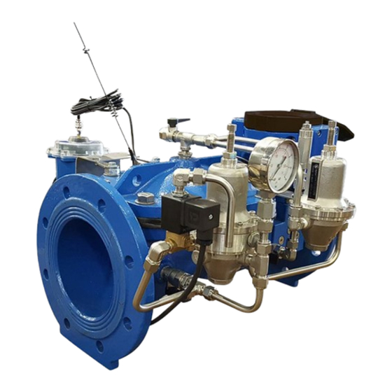
- Page 5 System Overview Ultraf system consists of the following components: ■ Valve (1) – Ultraf is compatible with a wide range of valve hydraulic applications. The appearance of the valves differs according to the model ordered. ■ Meter and controller unit (2) – installed on the valve, measures the flow and performs optional controls (see Ultraf Main Components...
- Page 6 Product Serial Number and Data The label located on the control panel cover indicates the product serial number (1). The serial number is the Ultraf default identification on the mobile device application. This serial number is used to identify the device. NOTE: The serial number is also located on the valve body as a permanent name plate tag.
-
Page 7: Package Contents
3 Package Contents Ultraf is delivered in a cardboard transport box with styrofoam padding and includes the following components: ■ 1 Ultraf configured with the selected output card (no card is optional) including batteries, 1 meter shilled 3mm cables; set to metric units. ■... -
Page 8: Installation
4 Installation This chapter reviews the tasks associated with installing and wiring Ultraf and includes: Mechanical Installation ■ Wiring Instructions ■ Mechanical Installation This section describes the tasks associated with Ultraf mechanical installation. Dimensions When preparing the pipe line for Ultraf installation, consider the following measurements according to the Ultraf model ordered: DN [mm] DN [inch]... - Page 9 General Installation Instructions This section provides recommended guidelines for installing Ultraf on a pipeline. NOTE: Install Ultraf upright in a horizontal mount or flowing upwards in a vertical mount. Make sure water flow is from the metering unit past the valve and out. Avoid air in the water. (see Ultraf Main Components on page ■...
- Page 10 Recommended Installation Examples The following examples provide recommendations for Ultraf optimal performance. A minimum of two pipe diameters after elbows (90°). A minimum of two pipe diameters after an isolating valve. A minimum of ten pipe diameters after pumps. A minimum of two pipe diameters after strainers. A minimum two pipe diameters after elbows (90°) in vertical installations.
- Page 11 Wiring Instructions Ultraf is delivered with one of the following control outputs. Each control output requires different wiring. The following sections provide wiring instructions for each control output: Ultraf Basic ■ Pulse Output ■ Analog Output ■ Solenoid Valve Output ■...
- Page 12 Pulse Output Ultraf Pulse Output sends a signal each time a pre-determined amount of water passes. The meter units and the (see Pulse Output Control on page amount (volume) are configured through the Raphael Ultraf mobile application 20). Pulse output is ideal when flow indication is delivered to: ■...
- Page 13 Analog Output Ultraf analog output provides a linear analog signal in a predefined flow spectrum. Analog output is ideal when flow indication is delivered to a reading device with analog input. Output specifications 4-20 mA current, requires external 12-36 VDC power supply. Wiring instructions 1.
- Page 14 Solenoid Valve Output This output type operates a solenoid valve and is used for pressure management applications. In this (see Pulse Output on page 12). configuration Ultraf is delivered with an additional pulse output Output specifications ■ Solenoid type – 12-18 VDC, latch ■...
-
Page 15: Setup And Configuration
5 Setup and Configuration This chapter reviews the tasks associated with monitoring and configuring Ultraf using a mobile device running the Ultraf application and includes: Mobile Application Installation ■ Ultraf Configuration ■ Mobile Application Installation To install Raphael Ultraf on a mobile device: ■... - Page 16 ■ UlraF app requires permission to access the mobile device Bluetooth. ■ Tap the button (4) to allow the ccept application to activate Bluetooth. Ultraf Configuration This section describes the Ultraf configuration process using Ultraf mobile application and includes: Connecting to Ultraf on page 16 ■...
- Page 17 The application automatically searches for Ultraf devices using Bluetooth. After the application detects a device, a check mark icon appears on the screen. NOTE: The mobile device must be within Bluetooth proximity to the valve and with a clear line of sight.
- Page 18 The detected Ultraf devices are displayed. Each device icon displays the following information: ■ Extension card used (1) – when applicable ■ Name of the device (2) – the default name is (see Product Serial the Ultraf serial number Number and Data on page The default name can be changed to a descriptive name (3) in the Settings screen.
- Page 19 Ultraf Basic Control This section describes the tasks associated with controlling Ultraf Basic Configuration, when no extension card is used. Monitoring Screen The following information regarding Ultraf connections is displayed: ■ Ultraf Name (1) – the default Ultraf name is the serial number of the device.
- Page 20 Pulse Output Control This section describes the tasks associated with configuration of Ultraf when a Pulse Output extension card is used. Monitoring Screen The following information regarding Ultraf connections is displayed: ■ Ultraf Name (1) – the default Ultraf name is the serial number of the device.
- Page 21 Analog Output Control This section describes the tasks associated with configuration of Ultraf, when an Analog Output extension card is used. Monitoring Screen The following information regarding Ultraf connections is displayed: ■ Ultraf Name (1) – the default Ultraf name is the serial number of the device.
- Page 22 Pressure Management Control This section describes the tasks associated with configuration of Ultraf when a Pressure Management extension card is used. Monitoring Screen The following information regarding Ultraf connections is displayed: ■ Ultraf Name (1) – the default Ultraf name is the serial number of the device.
- Page 23 Day Night Mode In this mode, Ultraf maintains high pressure within a time frame. During the rest of the day, Ultraf maintains low pressure. When the water flow exceeds the critical flow set point, Ultraf maintains high pressure regardless of the time of day.
-
Page 24: Operation
6 Operation This chapter reviews the tasks associated with the operation of Ultraf and includes: First Operation ■ Remote Monitoring ■ Local Monitoring ■ First Operation When operating Ultraf for the first time, make sure of the following: ■ Before installing Ultraf, flush the pipeline to remove scale, dirt and other particles that might affect valve performance. - Page 25 Local Monitoring The table below describes the information provided by Ultraf local display. Icon Description Notes Water Flow – when Ultraf fills up with water, When this icon alternates between this icon transforms from (a) to (b). (a) and (b), see Air in the Water on page This icon constantly rotates (c) to indicate that...
- Page 26 Icon Description Notes Main Battery Status – displays the main When this icon displays one line or lithium battery status. starts flashing, see Low Battery on page For battery replacement, see Main Lithium Battery Replacement on page Bluetooth Connection – displayed when bluetooth is connected.
-
Page 27: Maintenance
7 Maintenance Preventive Maintenance Winterizing In potentially freezing climates, Ultraf should be properly drained from standing water to avoid damage from expansion. Alternatively, freeze protection means can be used if operating in a sub freezing environment. Main Lithium Battery Replacement NOTE: Replacement of the lithium battery is done by an authorized Rphael personnel only. - Page 28 Secondary Battery Replacement Ultraf requires the following batteries per control configuration: ■ Ultraf Basic – none ■ Pulse Output – one 9VDC battery in the upper compartment (1) ■ Analog Output – none ■ Solenoid Output – two 9VDC batteries in both compartments To replace the battery: 1.
-
Page 29: Troubleshooting
8 Troubleshooting This chapter reviews problems that might occur during Ultraf operation and instructions for corrective actions. All of the following problems are indicated by the Alarm icon (1) on the Ultraf local display. Air in the Water Problem Description Air in the flowing water is indicated when the Water Flow icon stops rotating and shows that it is empty of water (2). - Page 30 No Analog Output Problem Description Analog signal is not received by the reading device connected to the Ultraf analog output (see Analog Output on page 13). Corrective Actions Verify the following: ■ Water is flowing through Ultraf in the proper direction and all measuring units are set to need. ■...
- Page 31 Damaged Cable or Extension Card Corrosion Problem Description Cables that are torn or damaged, and/or extension cards that are corroded. Corrective Actions Replace the damaged equipment. Proper cables and cards are available through Raphael authorized dealers. Low Battery Problem Description The Main Battery Status icon (1) on the local display drops to a single line and starts flashing.
-
Page 32: Specifications
9 Specifications ■ Ultraf is powered by a battery that lasts up to 10 years without maintenance. ■ Accuracy according to ISO 4064-2014 standard. ■ Multi-measurement worldwide system (gallons, m³, ft³, AI, AF). ■ Bluetooth communication with Raphael smartphone application for measuring unit preference selection ®... - Page 33 Headloss Curve FLOW RATE Accuracy Curve FLOW RATE DN [mm] DN [inch] Starting flow 22.3 35.4 88.6 141.8 Q2 (1) 44.7 70.9 177.2 283.6 Q2 (2) 63.0 250.0 78.8 312.5 R = Q3/Q1 According to ISO 4064-2014...
- Page 34 TALIS (“Information”). Any disclosure or distribution to any third party, reproduction, duplication publication or use of the Information in whole or in part for any purpose other than the conduct of business with TALIS or for the purpose stated herein is expressly prohibited and shall require the prior written approval from TALIS.
Need help?
Do you have a question about the Ultraf Pro and is the answer not in the manual?
Questions and answers