Table of Contents
Advertisement
Quick Links
Advertisement
Table of Contents

Related Manuals for Laski LS 150 T


Summary of Contents for Laski LS 150 T
- Page 1 OPERATING INSTRUCTIONS CHIPPER LS 150 T Orig. version: 08.2016...
-
Page 2: Foreword
Thank you very much that you have just purchased our product, the chipper LS 150 T. Our company has been engaged in production of equipment for wood residues crushing and disposal for many years and has gained considerable experiences in this field. -
Page 3: Table Of Contents
Contents ......................2 OREWORD ......................3 ONTENTS PRODUCT IDENTIFICATION ................5 WORK SAFETY INSTRUCTIONS ..............8 ......................8 TILISATION ....................8 LLOWED ......................8 ENERALLY ..................14 AFETY YMBOLS ..............15 RANSPORT OF RODUCT ANDLING ..................16 RECAUTIONS IN ESIGN ...................... - Page 4 ..............39 AILURES AND ROUBLESHOOTING ....................41 ASTE ISPOSAL ............. 41 SE OF THE CHIPPER EQUIPPED WITH A HITCH WARRANTY ......................44 SERVICE REPORT .................... 46...
-
Page 7: Product Identification
Product Identification Our product is identified with its serial number stamped in its type plate on the frame. Upon take-over of the product we recommend you to fill required data in the following form concerning the given product and your dealer. Type of product: ……………………………………………………. -
Page 8: Work Safety Instructions
Work Safety Instructions Utilisation This chipper, being coupled with a tractor three-point hitch, is designed for disposal of wood waste, twigs, barks, branch-wood and other above-ground biomass or for manufacture of chips from aforesaid materials and also for disposal of redundant timber, such as sticks, deals, pickets etc. The chipper can dispose all these materials with diameter up to 160 mm or flat boards and plates with thickness up to 60 mm. - Page 9 concerned controller in infeed direction this machine must stop loading materials and by its next pushing the loading rolls should turn back while being under permanent pressure (pushing). The controller frame have to be advanced in front of the hinged loading chute edge so that the attendant stops the loading rolls, or let them turn back, at pushing by using parts other than hands (e.g.
- Page 10 While working the chipper should rest on the ground. Keep this machine beyond children's and unauthorised person's reach. Avoid their attendance while chipping. When using the chipper without any container or closed bin, keep anybody beyond the area where chips are being thrown. When using the chipper with such a bin, never look inside if the chipper is still working.
- Page 11 While chipping the operator is obliged: to use only such a chipper which is in optimal operating condition, not damaged through transport, storage of from previous operation, to check functions of all controls and safety elements, particularly the controller frame, before putting the chipper into operation, ...
- Page 12 any of important parts. Pay regular attention to all joints and bolts. Keep them properly tightened. Do not put any objects or tools on the machine. The manufacturer does not bear responsibility for any damages or injures caused to the third persons or to other equipment resulted from disobedience to instructions given in this manual.
- Page 13 Before transport on public roads: Set the machine in the transport position, i.e. with its discharge duck tilted backwards and locked against motion. Be aware that traffic lights must remain visible. Couple the chipper to a towing vehicle properly and check proper pin coupling.
-
Page 14: Work Safety Symbols
Work Safety Symbols This article introduces work safety symbols (pictographs) used on this machine. Under the given pos. number there is their location on the machine. These work safety symbols warn the operator against risks connected with the machine use. Your respect to the symbol meanings is a precondition for your work safety. -
Page 15: Transport Of Product/Handling
Warning! Hot parts. Warning! Turning Warning! Ejected Warning! Close all Wear personal part is running out. objects hazard. Keep guards before protective away. starting the machine. equipment. Keep safety distance. Warning! Risk of Warning! Rotating Warning! Hazard of Warning! Accident high-pressure liquid rolls. -
Page 16: Precautions In Design
Precautions in Design This product is equipped with hoods and covers protecting rotary and hot parts against touching. Protective covers are usually fixed, bolted down on framing. Ignition box for starting, completed with a removable switch key. Any confusion with another ignition keys is not possible. - Page 17 Safety pin of the chipping device rotor serves for rotor blocking at blades exchange and servicing. The pin is chained on the machine side. A hole for pin inserting is covered with a rubber stopper. The chipping device is blocked if the pin is inserted into a bush on the rotor.
-
Page 18: Controls
Emergency STOP button blocks loading immediately – similar function as that of the safety frame. Controls Ignition box – used for supply and control of the safety circuit. CAUTION: Despite the fact that this machine is not equipped with any driving engine, its ignition key, analogously to engine starting, must be set in the START position and afterwards in the RUN position. -
Page 19: Use
Controller of loading speed - installed under a hinged part of the loading chute Change of loading roll speed Speed regulation in range from 0 to 40 m/min Emergency STOP button blocks loading immediately – similar function as that of the safety frame. - Page 20 locking of hinged part of loading chute in transport position fitting of triangular symbol for slowly vehicles on framing It is strictly forbidden to transport the chipper with the PTO shaft on. It is not allowed to transport any objects or loads on the chipper. Never couple another machine or implement to the chipper.
-
Page 21: Storage
Storage Store the chipper always in a dry shelter to protect it against weather effects. During storage keep the switch key separately. Keep the stored machine beyond unauthorised persons reach. Before storage clean all parts of the machine. For cleaning use pressure water. Should the water be in the chipping device space, wipe it off and let it dry. - Page 22 Avoid spillage at filling hydraulic oil. Use always a proper filling funnel. If any oil is spilled or overflowed then wipe off the spots immediately. Do not use petrol or similar inflammable matters as a cleaning agent. It is strictly forbidden to do any technical changes on the machine without any prior approval of the manufacturer in writing.
-
Page 23: Coupling To Tractors
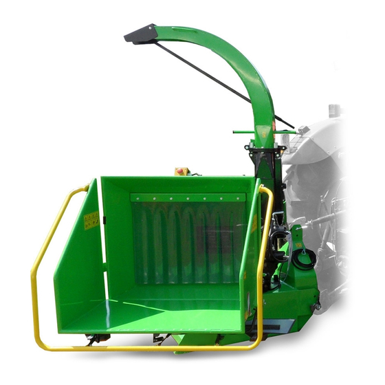
Coupling to Tractors This chipper can be coupled to a tractor which is equipped with a three-point hitch, category I or II and a PTO shaft. This hitch coupling can be done from outside by means of locking pins, Ø 27 mm for the category II or Ø 22 mm for the category I. The chipper is height-adjustable (according to tractor tires size) when inserting pins in other holes, see following figure. -
Page 24: Putting Into Operation
When coupling the chipper to a tractor just let the lower drawbars go down in a similar height as the coupling pins are. Go back slowly with the tractor to the chipper hinge. While coupling the chipper no person is allowed to stand between the chipper and the tractor Lock the lower drawbars by means of locking pins in the chipper hinge. -
Page 25: Chipping
Carry out a functional check of the safety frame of the loading chute. Set the lever in the infeed position and the loading rolls start turning (loading). By first pushing the frame the rolls should stop loading immediately (EMERGENCY STOP), the next pushing behind the chute edge (D) brings their reverse turning. - Page 26 When loading materials and during operation of the chipper the attendant should always stand in the attendant's place, see fig. Having turned the chipping device on wait for speed stabilization. With that you may soever increase or reduce the tractor PTO shaft speed. For correct chipping functions it is necessary if the tractor PTO shaft speed is 540 rpm(1000 rpm).
- Page 27 Be careful while loading since materials may unexpectedly move in unwished directions. In case of two attendants it is necessary to make simple signals clear before working. During operation it is not easy to make any agreements because of operating noise. Observe the working area.
- Page 28 Blunt blades are evident on chipped edges which are not clean but broken. The optionally used breaker for crushing brings increased costs for energy consumption. The breaker should not be used for small and short wooden pieces, leaved or coniferous branch wood (with low weight) which may bring fouling due to shortage of woody mass.
-
Page 29: Putting Out Of Operation
Putting out of Operation If you want to stop chipping: In case of loaded material wait for emptying of the loading chute. Wait for emptying of the discharge duct. Turn the tractor PTO shaft off. Warning! The cardan shaft is equipped with a freewheel clutch. When turned off, the rotor of the chipping device runs out –... -
Page 30: Technical Description
Technical Description This machine consists of following main parts: chipping device - loading chute - loading rolls - chipping wheel - discharge duct frame Chipping Device Loading chute The loading chute is made of welded steel plates consisting of two parts: fixed and hinged one. -
Page 31: Frame
The chipping wheel is installed in a rigid frame and protected by a steel plate. Its protective shield consists of two parts and particular parts are bolted together. By safety reasons the upper part is protected with a terminal switch for turning the drive off if the shield was opened or got loose. -
Page 32: Maintenance
ISO VG 46, ISO 6743/4 typ HV CETOP RP 91 H Category HV DIN 51 524 část 3-HVLP Poclain P00552-13P Capacity of hydraulic oil tank: Gear Oil SAE 80W/90, API GL-4 Recommended amount of gearbox 1,5 + 1,5 Maintenance Any servicing of the chipper should be carried out by authorised persons only. - Page 33 Grease cups of loading roll slides Grease cups of swivel base (LTA 3EP MOL Lition) (LTA 3EP MOL Lition) Oil change in gearboxes Gearbox oil - SAE 80W/90, API GL-4 Oil charge – 1,5l per 1 gearbox, in total 3l oil Oil change after 2500 working hours or 5 years...
-
Page 34: Blade Grinding
Blade Grinding Blades, fitted on the chipping wheel, are double-sided, i.e. reversible if one side is blunt. Blades edge regrinding requires high demands for keeping cutting edge shape. While grinding it is necessary to keep its optimal geometry, see following figure. Proper shapes prolong blade service life. -
Page 35: Chipping Adjustment
Max. wear/grinding of cutting edge Chipping Adjustment Optimal operation of the chipping device requires proper setting of a clearance between the blade and the opposite cutting edge. This distance should be set (see following figure) and checked after fitting ground blades, then it grows with their wear and chipped branches may be squeezed between the blade and the opposite edge. -
Page 36: Nostress System - Speed Regulation
NOSTRESS System – Speed Regulation This system is intended for overload protection of the combustion engine consisting of an electronic control unit and a speed sensor installed on the rotor shaft No Stress ON – the machine chipping with automatic regulation the infeed of the material ( there is no overload of the combustion engine consisting) -
Page 37: Nostress System Protection Against Overvoltage
Location of sensor under hood NOSTRESS system protection against overvoltage Overvoltage occurrence in the electric installation blows the fuse and breaks the TVS diode (Transient Voltage Suppressor / Transil) used to protect sensitive NOSTRESS electronics against voltage spikes. Should the fuse (7,5 A) be blown again, first replace the damaged TVS diode and then put a new fuse. -
Page 38: Maintenance Intervals
Maintenance Intervals Electric Protect all wires against contact with oil products. Keep all Installation elements clean and avoid any damage of wires - short circuit risk. All connections must have clean and proper contact surfaces to avoid intermediate resistance at a wrong contact point. -
Page 39: Checking, Oil Exchange
Checking, Oil Exchange Operation Component Interval (hrs) 1000 2500 5000 Cleaning Hydraulic oil tank Hydraulic oil filter Checking Hydraulic oil in tank Exchange Hydraulic oil in circuit Exchange Oil gear years) clean daily under special conditions clean every 4 – 5 hrs under extreme dusty conditions (**) (***) see recommended oils... - Page 40 Throttle valve closed Check up manual speed regulation for loading Control lever in wrong Press the lever in loading direction position Failure of NOSTRESS Measure voltage on coil of electromagnetic valve; it should be 0 system at max. speed Faulty coil of Coil replacement electromagnetic valve...
- Page 41 Bearing loosened Tighten up bearing housing bolts with required torque Bearing worn Replacement Waste Disposal Any waste materials resulting from the machine operation should be disposed in accordance with laws and regulations applicable in the given country. Protect nature and water resources against used oil and filter elements. Any parts of the machine should be disposed in accordance with laws and regulations applicable in the given country.
- Page 42 Conditions for use of the hitch for towing of a trailer during chipping The hitch, mounted on the chipper rear, is intended solely for towing of a trailer during chipping, i.e. for gathering of ejected wooden chips. It is forbidden to couple a trailer to the chipper for transport on public roads While working on or nearby public roads the towing tractor must be equipped with a beacon of orange colour for flashing and the chipper must be equipped with 2 safety plates with red-white hatching, sight lights, reflector glasses and...
- Page 43 Due to low permissible vertical coupling load it is forbidden to couple trailers, resp. semi-trailers, with axles centrally mounted. The trailer to be coupled must be in good technical condition and its brakes, tyres and lights must by fully functional. The trailer must comply with applicable EU standards and local regulations.
-
Page 44: Warranty
brakes and lights must be fully functional and the chipper engine must be turned off. 16. If the chipper works in the same workplace for a longer time, it is necessary, before its displacement, to check out safe coupling of the trailer, its air-brake couplers and electric plug and to test their functionality. - Page 45 This warranty does not cover any damage of machine caused by usage of unoriginal spare parts. This warranty does not cover consequences resulted from weather effects. Any warranty claims must be submitted in writing with papers concerning acceptance for warranty or post-warranty repair.
-
Page 46: Service Report
Service Report... - Page 47 Service Report...
- Page 48 Service Report...
Need help?
Do you have a question about the LS 150 T and is the answer not in the manual?
Questions and answers