Table of Contents
Advertisement
Quick Links
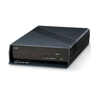
Communications Adapter Plus (CAP)
CUSTOMER
SUPPORT
INFORMATION
C A P
Order toll-free in the U.S. 24 hours, 7 A.M. Monday to midnight Friday: 877-877-BBOX
FREE technical support, 24 hours a day, 7 days a week: Call 724-746-5500 or fax 724-746-0746
Mail order: Black Box Corporation, 1000 Park Drive, Lawrence, PA 15055-1018
Web site: www.blackbox.com • E-mail: info@blackbox.com
SEPTEMBER 1995
R E S E T
T X B R X B
T X A R X A
CMA02A
CMA02C
P W R
Advertisement
Table of Contents

Related Manuals for Black Box CMA02A


Summary of Contents for Black Box CMA02A
- Page 1 Order toll-free in the U.S. 24 hours, 7 A.M. Monday to midnight Friday: 877-877-BBOX SUPPORT FREE technical support, 24 hours a day, 7 days a week: Call 724-746-5500 or fax 724-746-0746 Mail order: Black Box Corporation, 1000 Park Drive, Lawrence, PA 15055-1018 INFORMATION Web site: www.blackbox.com • E-mail: info@blackbox.com...
- Page 2 FEDERAL COMMUNICATIONS COMMISSION CANADIAN DEPARTMENT OF COMMUNICATIONS RADIO FREQUENCY INTERFERENCE STATEMENTS This equipment generates, uses, and can radiate radio frequency energy and if not installed and used properly, that is, in strict accordance with the manufacturer’s instructions, may cause interference to radio communication. It has been tested and found to comply with the limits for a Class A computing device in accordance with the specifications in Subpart J of Part 15 of FCC rules, which are designed to provide reasonable protection against such interference when the equipment is operated in a commercial environment.
-
Page 3: Table Of Contents
COMMUNICATIONS ADAPTER PLUS (CAP) CONTENTS 1.0 SPECIFICATIONS.............................3 2.0 INTRODUCTION.............................4 Conversions Possible with the CAP ....................4 3.0 INSTALLATION ............................6 Installation Checklist........................6 Installing the CAP...........................7 3.2.1 AC Power..........................7 3.2.2 Cable Requirements ......................7 DIP Switch Settings.........................8 Setting the Mark and Space Parity ....................10 CAP to Device Connection ......................14 4.0 TROUBLESHOOTING ..........................15 Diagnostic LEDs ...........................15... -
Page 4: Specifications
CHAPTER 1: Specifications 1 Specifications Protocol — Asynchronous only Speed — 45.5 bps to 38.4 Kbps Hardware, X-ON/X-OFF, ENQ/ACK Flow Control — Indicators — RXD and TXD for Ports A and B; Power Interface — RS-232/CCITT V.24 configured as DTE Connectors —... -
Page 5: Introduction
COMMUNICATIONS ADAPTER PLUS (CAP) 2 Introduction The Communications Adapter Plus (CAP) lets two cannot transmit data. A device attached to the CAP is asked to stop transmitting when incompatible devices that use RS-232 interfaces only 256 bytes of unused space remain in communicate with each other. - Page 6 CHAPTER 2: Introduction Common rates between 45.5 and 38,400 bps are • Transmission Mode — This is the protocol available. See the baud-rate chart (Table 3-4) for defining how information is transmitted over specific rates available. Some other baud rates the RS-232C interface.
-
Page 7: Installation
COMMUNICATIONS ADAPTER PLUS (CAP) 3 Installation Before you install the CAP, you should plan how to Baud Rate and Data Code program the unit for your application. The DIP Switch checklist in Section 3.1 will help you plan your Positions Device A Device B installation. -
Page 8: Installing The Cap
CHAPTER 3: Installation DIP Switch 3.2 Installing the CAP Positions Device A Device B Before the CAP can be installed, you must program Transmission it to match your specific application. You must set Mode (Full internal DIP switches and jumpers. This is a very duplex, half- simple procedure if you first fill out the checklist in duplex, or... -
Page 9: Dip Switch Settings
COMMUNICATIONS ADAPTER PLUS (CAP) Table 3-1. Pins Supported by the CAP NAME DESCRIPTION SOURCE Data Carrier Detect Receive Data Transmit Data Data Terminal Ready Signal Ground DTE and DCE Data Set Ready Request to Send Clear to Send Ring Indicator 3.3 DIP Switch Settings If any switch positions are changed with the unit turned off, the unit is automatically set to those... - Page 10 CHAPTER 3: Installation Table 3-2 defines the function of each of the unit's switches. Tables 3-3 through 3-8 give switch settings for particular applications. Table 3-2. Switch Functions SWITCH FUNCTION Port A word structure and buffer flow control Port B word structure and buffer flow control Port A baud rate and data code set Port B baud rate and data code set Ports A and B RS-232 lead options, equipment type,...
-
Page 11: Setting The Mark And Space Parity
COMMUNICATIONS ADAPTER PLUS (CAP) NOTE • For Mark Parity — Mark parity can be used only if your device is using a word structure For all hardware flow control, CTS and containing one stop bit. Set Positions 1 and 2 DTR Switch 7 options must NOT be in ON (2 stop bits). - Page 12 CHAPTER 3: Installation Table 3-4 (continued). Switch S3 (Port A) and S4 (Port B) Settings for Baud Rate and Data Code Set OPTION SWITCH POSITION SETTING Baud Rate 164.82 1371.54 1200 1037.92 164.82 134.28 110.35 74.42 67.14 55.82 45.5 Data Code Set ASCII EBCDIC TRANSCODE...
- Page 13 COMMUNICATIONS ADAPTER PLUS (CAP) NOTE NOTE The selected baud rate can be within Make sure Switches S1 and S2 are set 4% of your desired rate and still allow for the correct number of data bits for error-free communication. the particular Data Code set chosen (Table 3-3 and the code set list in Section 3.4).
- Page 14 CHAPTER 3: Installation Table 3-6. Switch S7 Settings for the CAP OPTION SWITCH POSITION SETTING RI Input Port A RS-232 RI Connected (custom programming only) Forced Inactive (High) DTR Output Port A Controlled by software (hardware flow control) Forced always active (High) DCD Input Port A RS-232 DCD Connected input enables Receive Data (Half-duplex)
-
Page 15: Cap To Device Connection
COMMUNICATIONS ADAPTER PLUS (CAP) Table 3-7. DSR Jumper Settings for CAP FUNCTION JUMPER POSITION DSR Jumper for Port A — No Connection W2 — AB DSR Jumper for Port A — DSR Output Always Active W2 — BC DSR Jumper for Port B — No Connection W3 —... -
Page 16: Troubleshooting
CHAPTER 4: Troubleshooting 4 Troubleshooting If you have difficulty with your application, the 3.TXA and TXB — If the CAP receives data when its receive enable is active, it puts the data in its problem may be in either the unit's configuration internal buffer. -
Page 17: Code-Set Conversion Tables
COMMUNICATIONS ADAPTER PLUS (CAP) 5 Code Set Conversion Tables This section contains tables that give the called a special figure five (SF5). A lower-case "a" in hexadecimal number (followed by "H") for a ASCII (061H) would be converted to a capital "A" character in the ASCII, EBCDIC, Transcode, in Baudot (03H), because Baudot does not support Baudot, and Ticker Tape codes. -
Page 18: Upper-Case Letters
CHAPTER 5: Code Set Conversion Tables 5.2 Upper-Case Letters All upper-case letters can be converted, so only one letter is given in the "Character or Control" column. ASCII EBCDIC Transcode Baudot Ticker Tape Character or Control 041H 0C1H 001H 003H 003H 042H 0C2H... -
Page 19: Special Printable Characters
COMMUNICATIONS ADAPTER PLUS (CAP) 5.4 Special Printable Characters Any special printable character that cannot be converted is changed to another character that is a valid member for that code set. The common character dash (-) is used, except for ticker-tape code that can't be converted. -
Page 20: Control Codes
CHAPTER 5: Code Set Conversion Tables 5.5 Control Codes Any control code that cannot be converted is discarded and shown as an OFFH. ASCII EBCDIC Transcode Baudot Ticker Tape Character or Control 006H 02EH 0FFH 0FFH 0FFH 007H 02FH 00DH 00BH 0FFH 008H... -
Page 21: Ticker Tape
COMMUNICATIONS ADAPTER PLUS (CAP) ASCII EBCDIC Transcode Baudot Ticker Tape Character or Control 0FFH 004H 0FFH 0FFH 0FFH 0FFH 034H 0FFH 0FFH 0FFH 0FFH 027H 0FFH 0FFH 0FFH 0FFH 014H 0FFH 0FFH 0FFH 0FFH 009H 0FFH 0FFH 0FFH 01EH 035H 0FFH 0FFH 0FFH... - Page 22 CHAPTER 5: Code Set Conversion Tables Changed Ticker Char ASCII Baudot Tape EBCDIC Transcode Description Spare code Letters dot "P" with "R" below "W" with "I" below "R" with "T" below Special Figure 5 Lower Case "C" Figures Dot Lower Case "s" "1"...
-
Page 23: Appendix: Optional Cables
CAP AND USER PROGRAMMABLE CAP Appendix: Optional Cables This appendix shows the special pinning required The diagrams are set up so that the left side of the for the CAP to operate in particular applications. If illustration shows pinning on one end of the cable, your application matches the caption of one of the while the right side shows pinning on the other pinning diagrams below, make sure the cable you... - Page 24 APPENDIX: Optional Cables DCE Device AT SERIAL PORT DB9* DB9M DB25M DB9M DB9F *Must specify gender type when ordering. Figure A-3. CAP-to-AT Cable Figure A-4. CAP-to-DCE Cable (DB9 to DB9 Cable for AT). (DB9 to DB9 Cable). (EHN025) (ECN12D) PC SERIAL PORT DB9M DB25F 21 SQD...
- Page 25 CAP AND USER PROGRAMMABLE CAP CAP DB9 female Signal Direction Input Input Output Output Output or N/A Output Input Input Figure A-6. RS-232 Port(s) Pinouts and Signal Flow for Both CAP Ports.
- Page 26 Switches S1 (Port A) and S2 (Port B) Switch S5 Settings S3 and S4 Switch Settings for Baud Rate and Data Code Set POSITION WORD STRUCTURE RS-232 lead options, equipment type, transmission mode, 1 stop bit and buffer allocation POSITION Baud Rate with Baud Rate with 1 1/2 stop bits...
- Page 27 © Copyright 1995. Black Box Corporation. All rights reserved. 1000 Park Drive • Lawrence, PA 15055-1018 • 724-746-5500 • Fax 724-746-0746...
Need help?
Do you have a question about the CMA02A and is the answer not in the manual?
Questions and answers