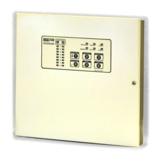
Summary of Contents for Noby 448
-
Page 1: Table Of Contents
TABLE OF CONTENTS Page Getting Started Power Supply Unit Remote Keypad Bus Inputs & Outputs User Keypad Functions Engineer Keypad Functions Troubleshooting Specification LED Indications Connection Diagram Keypad Function Chart Noby-448 Installation & Programming Instructions (Rev.5) Page 1 of 12... -
Page 2: Getting Started
GETTING STARTED We strongly recommend that the Noby-448 is first powered up with all 4K7 End Of Line resistors fitted at the panel as supplied by the factory. In this way you can gain confidence that the panel is operating correctly before introducing detector and sounder circuits. -
Page 3: Power Supply Unit
Ensure correct connectivity A to A and B to B. Each Noby-448RKP must be set to a unique dip-switch address in the range 2 to 4 (the factory setting is address 2). Note that address 1 is reserved for the internal lid mounted keypad on the Noby-448. -
Page 4: Inputs & Outputs
Zone Detector Circuits The Noby-448 requires that each detector zone is terminated with a 4k7 End Of Line resistor. This EOL resistor is necessary to facilitate open circuit, short circuit and head removal monitoring. The total current drawn by the detectors on each circuit must not exceed 2mA, which means that 20 detectors can be connected to each zone (based on a typical 100uA maximum per detector). -
Page 5: User Keypad Functions
The system will revert back to normal standby mode after 90 seconds of panel inactivity (i.e. no keypad operations or zone activations). Any fire alarm generated from a non-test zone will cause the system to abort the test and give the appropriate fire response. Noby-448 Installation & Programming Instructions (Rev.5) Page 5 of 12... -
Page 6: Engineer Keypad Functions
This function is used to identify which sounder circuit is in fault condition. The sounder circuit in fault is indicated by means of the yellow zone fault LEDs 1 thru 8. Key [5] to Quit and revert back to normal standby mode without updating the E2PROM. Noby-448 Installation & Programming Instructions (Rev.5) Page 6 of 12... -
Page 7: Troubleshooting
Continuous Zone Faults And Sounder Faults? • If the Noby-448XT module is fitted then check that the 10-way ribbon cable connector is secure. • If the Noby-448XT module is not fitted, then ensure that the programmable option ‘Configure Noby-448XT 4- Zone Extender’... - Page 8 • Refer to the section ‘Remote Keypad Bus’ (page 3), in particular: o Check that the DC supply voltage at each Noby-448RKP exceeds 12.0 volts in normal standby operation, and 10.0 volts during the 3 second Reset phase (all LED’s illuminated).
-
Page 9: Specification
20mm Slow Blow 30VAC Transformer Secondary 20mm Slow Blow Standby Battery Current: • Noby-448 4 zone main panel 4 zone + 4 sndr EOL resistors fitted 8 zone + 8 sndr EOL resistors fitted • Noby-448 4+4 (Noby-448XT fitted) all LED’s off •... -
Page 10: Led Indications
Isolate LED One or more zones isolated Test LED 7 day fire test reminder * * Zone Faults are non-latching as supplied from the factory. Latching function is a programmable option. Noby-448 Installation & Programming Instructions (Rev.5) Page 10 of 12... -
Page 11: Connection Diagram
Noby-448 Installation & Programming Instructions (Rev.5) Page 11 of 12... -
Page 12: Keypad Function Chart
Noby-448 Installation & Programming Instructions (Rev.5) Page 12 of 12...
