
Subscribe to Our Youtube Channel
Related Manuals for BilJax Multi-Stage AS-2100

Summary of Contents for BilJax Multi-Stage AS-2100
- Page 1 ASSEMBLY INSTRUCTIONS PRINTED IN USA P/N: LL-204-51 Assembly Instructions Include: Step 1: Site Preparation Step 8: Bracing Step 2: Leg Assembly Step 9: Guard Rail Installation Step 3-7: Setting the Stage Step 10: Stairs...
-
Page 2: Site Preparation
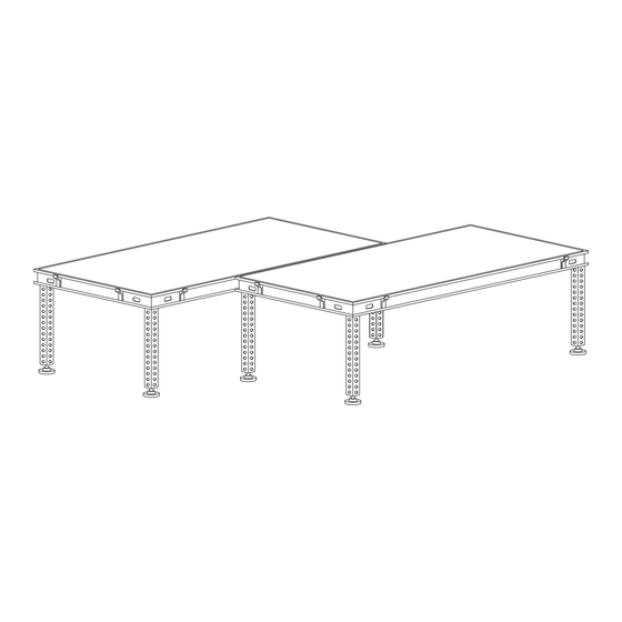
Step 1 Site Preparation A. Determine the exact location where the stage will be erected. B. For outdoor stages, mudsills are required to distribute the weight (125 PSF to 150 PSF) on the stage legs. This will prevent the legs from sinking and ease the leveling of the stage. - Page 3 Step 3 Setting the Stage, Continued A. Set first stage section in back left-hand corner of stage site. Any corner may be used as a starting point when using 4’ x 4’ decks exclusively. B. Align the stage section so that the connecting brackets facing up are inside the starting area and the connecting brackets facing down are outside, as shown in the diagram.
- Page 4 Step 4 Continued D. Install Leg Brackets, as necessary. Leg brackets (shown at right) should be installed into empty leg sockets along the perimeter to prevent stage sections from sliding. Leg brackets are installed in the same way as stage legs, as shown in Step 3. Step 5 The modular design of the AS-2100 allows stage rows to be staggered.
- Page 5 2. When using double diagonal bracing, at least one of the braces should span the connection between the 1-1/2” and the 1-3/4” telescoping sleeve. WARNING Always consult the BilJax Application Department for proper bracing requirements when stage height exceeds 5’6”. (1.800.537.0540)
- Page 6 Step 9 Guard Rails Each guard rail section has two T-Locks to secure the guard rail to the Multi-Stage. To install guard rail: A. Set the lower lip of the guard rail lock inside the C-Channel along the perimeter of the Multi- Stage.
- Page 7 Step 10 Stairs Each set of stairs requires a T-Lock adapter to secure the stairs to the Multi-Stage. To begin, attach the T-Lock adapter to the stair assembly using the bolts provided. To install stairs: A. Set the lower lip of the lock inside the C-Channel along the perimeter of the Multi-Stage. B.
-
Page 8: Replacement Parts
Replacement Parts Call BilJax at 1.800.537.0540 or contact your regional BilJax representative to order replacement parts. Part Number Description 0105-22-___ Stage Section - 4’ x 4’ 0105-20-___ Stage Section – 4’ x 8’ 0065-0299-___ Leg – 1-3/4” 0065-0298-___ Leg – 1-1/2” Telescoping 0105-06-102 Horizontal Brace, 4’...
Need help?
Do you have a question about the Multi-Stage AS-2100 and is the answer not in the manual?
Questions and answers