Table of Contents
Advertisement
Quick Links
Advertisement
Table of Contents

Summary of Contents for ASCEL Electronic AE20125
- Page 1 Æ20125 10 MHz Sweep DDS Function Generator Assembly and Operation Manual...
- Page 2 REV 3.1 EN © 2015 Ascel Electronic...
-
Page 3: Table Of Contents
Table of Contents Safety Information..............ii Handover of a Device Built From a Kit........iv Intended Use................iv ESD Warning................v AE20125 Sweep DDS Function Generator.......1 Circuit Description..............2 Soldering..................4 Component Reference..............6 Assembly..................14 Calibration................17 Troubleshooting Checklist............18 Power Supply................20 Case Mounting.................21 Operation..................23 Circuit Diagram...............33 Bill of Materials...............35 Component Placement Diagram..........38... -
Page 4: Safety Information
Warning Please read this manual before you assemble and use this kit. Keep it accessible for all users at all times. Safety Information Know and follow the applicable regulations for electric devices in your region. In Germany, these especially VDE 0100, 0550/0551, VDE 0700, VDE 0711 and VDE 0860. - Page 5 •Always check if the device is suitable for the intended purpose before putting the unit in use. Seek assistance from a qualified professional or the manufacturer if you are not sure. • The manufacturer assumes no liability for errors made during assembly or operation.
-
Page 6: Handover Of A Device Built From A Kit
Handover of a Device Built From a Kit (in countries where applicable) If you hand over a device built from a kit, you legally become the manufacturer. This means you are responsible for complying with the appropriate regulations for electronic devices. -
Page 7: Esd Warning
ESD Warning What is ESD? ESD (Electrostatic Dis- charge) is the sudden flow of electricity between two Warning symbol for an objects caused by contact electrostatic sensitive device or an electrical short. It can reach very high voltages of many kV. In some cases even over 100kV! Causes of ESD The main cause of ESD events is static electricity. -
Page 8: Ae20125 Sweep Dds Function Generator
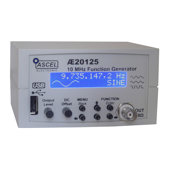
AE20125 Sweep DDS Function Generator The AE20125 Function Generator is capable of producing sine, square and triangle signals with an output frequency from 0.1 Hz to 10 MHz , continuously adjustable in 0.1 Hz step over the entire range. The maximum amplitude is 5Vpp. The DC offset is adjustable from -5V to +5V. -
Page 9: Circuit Description
Note: for a comprehensive overview of DDS, an excellent document is available from Analog Devices The heart of the AE20125 is the AD9833 from Analog Devices (IC2). It is capable of producing sine, square, and triangle wa- veforms. The 25 MHz crystal oscillator Q1 provides the master clock for the DDS. - Page 10 The reconstructed waveform from the AD9833 is fed into the output amplifier. The high speed current feedback op amp LM6181 (IC3) amplifies the signal to an amplitude of 5Vpp. The high bandwidth of 100 MHz, 100mA output drive capability and the very high slew rate of 2000V/µs makes the LM6181 an ideal choice for this application.
-
Page 11: Soldering
Soldering Please read the following pages if you are not yet experienced in soldering. Good soldering is a matter of practice! Practice on old boards until you feel confident before assembling the kit. • The parts are mounted on the silkscreen side of the PCB. Except parts whose designators ends with an asterisk (like S1*). - Page 12 • When soldering active components (ICs, Transistors, LEDs...), it is very important to prevent overheating the components. They should be soldered in no more than about 5 seconds. In addition, it is important not to confuse the polarity! See the next chapter on individual component types and their correct orientation.
-
Page 13: Component Reference
Component Reference 1 Resistors To save PCB space, the resistors are mounted standing. To install: 1. Bend the leads in form and put the resistor through the corresponding mounting holes. 2. Bend the leads aside to prevent the resistor from falling out. 3. - Page 14 Color Codes: Color Digit Multiplier Tolerance ± in % None Silver Gold Black Brown Orange Yellow Green Blue 0.25 Purple Grey 0.05 White 2 Capacitors / Electrolytic Capacitors Capacitors are soldered the same way as resistors. Electrolytic capacitors are polar. They must be mounted in the correct orientation! They will be destroyed when installed in reverse polarity and may even burst! Please keep in mind that different manufacturers mark the...
- Page 15 Capacitance Identification A three-digit number without letters is the capacitance in pF, where a are the first two digits calculated this way: a∗10 and b is the third digit (105 become 10*10 pF = 1µF). One- or two-digit numbers states the capacitance directly in pF. A number including the letter "n"...
- Page 16 3 Diodes The circular band on diodes identifies the cathode (negative terminal). The bar depicts the cathode in the symbol. The positive terminal is called the anode. Diodes are mounted horizontal. Try not to heat up the body of the diode while soldering. 4 LEDs LEDs (light-emitting diodes) must be soldered with respect to the correct polarity as well.
- Page 17 5 IC-Sockets / ICs With ICs (integrated circuits), it is essential to observe correct polarity. Most ICs will be damaged or destroyed when mounted incorrectly. The mark on the silkscreen must match the notch on top of the IC. Pin numbers are counted counter-clockwise, starting from the notch.
- Page 18 6 Transistors Transistors must be mounted in the correct orientation. The flat side of the transistor must match the correspondent side in the silkscreen drawing. The leads may not cross. Note: field-effect transistors (FETs) are extremely sensitive to ESD. 7 Crystal The polarity of the crystal is not relevant, but the bottom side of the package is conductive.
- Page 19 8 Inductors Inductors are soldered just like resistors. They also use similar color-coding, usually with four bands. The first two are the base value (see table below), the third is the multiplier to the base value and the fourth is the tolerance. The inductor value base value * multiplier [ ±...
- Page 20 9 Relay The side of the relay marked with a bar corresponds to the side marked with a "1" on the silkscreen. In contrast to the IC marking, the notches have no meaning! 10 Crystal oscillator Unlike crystals, oscillators are polar. Pin 1 is identified by the pointy edge.
-
Page 21: Assembly
Assembly General note It is essential to work precisely and systematically to minimize the possibility of faults. Check every step, each component placement and orientation, and any solder joint. Follow the assembly order given in the manual. Take your time - it takes longer to troubleshoot than to prevent faults by working accurately. - Page 22 Mounting 1. Solder all of the parts without an asterisk on the side of the board where the silkscreen is. (see the picture on the next page). Wait to insert IC1 in the socket until you have finished the assembly. After all the parts on this side are soldered, please examine the board carefully for shorts, bad solder joints and correct placement.
- Page 23 Finished Component Side Finished Solder Side, without the LCD LCD Mounting...
-
Page 24: Calibration
Calibration An oscilloscope or a multimeter capable of measuring the peak-to-peak value of a square wave is needed for the calibration. DC Offset Symmetry To adjust the DC offset: 1. Set the output amplitude potentiometer to minimum 2. Set the DC offset potentiometer in mid-position. 3. -
Page 25: Troubleshooting Checklist
Troubleshooting Checklist Check and tick off every step. □ Is the polarity of the supply voltage correct? □ Is the supply voltage in the range of 14-18V when the device is turned on? □ Are all resistors placed right? Check the color bands. □... - Page 26 □ Are there solder bridges on the solder side of the PCB causing shorts? They are easier to find if you hold the PCB toward bright light. □ Are there bad/cold/dry solder joints? Jiggle component leads at the solder joint with a pair of tweezers. Re- solder them if any move.
-
Page 27: Power Supply
Power Supply A 14V-18V DC power supply capable of providing at least 300mA is required. The optional AC adapter, batteries or any other supply that meets this criteria can be used. Warning: An AC power supply may not be used! Note: It is advisable to use a current limiting lab power supply when switching on for the first time. -
Page 28: Case Mounting
Case Mounting Note: This describes the optional case available with the kit. The case is provided with all necessary cut-outs and labels. 1. Put the extension caps on the tact switches. 2. Join the front panel and the PCB and insert both in the respective brackets. - Page 29 4. The two highlighted brackets on the front side of the top case part should be broken off as they will interfere with the heat sink and C11. 5. Solder four pieces of wire, about 15cm (6") long, to the two Cinch connectors and their ground leads.
-
Page 30: Operation
Operation Menu Structure... - Page 31 Basic Operation Frequency The frequency is adjusted with the arrow keys. The active digit is always blinking. Its value can be changed with Press to set the active digit. Waveform Press to get to the waveform selection menu. FUNCTION/Enter Press to select either sine ( ), triangle ( ) or...
- Page 32 Menu Control To access the main menu, press . See the diagram for MENU/Back the menu structure. In all menus, the top line of the display shows the active menu title or the menu item that is being adjusted. The bottom line shows the active menu item or the value of the menu item that is being adjusted.
- Page 33 2 MODULATION The AE20125 is capable of frequency (Frequency Shift Keying, FSK) and phase modulation (Phase Shift Keying, PSK). For the modulation source, an internal frequency can be selected or the external input may be used. The MODULATION menu is used to adjust the modulation parameters.
- Page 34 2.4 INT FREQ When internal modulation source is selected, the frequency of the modulation can be adjusted here. 2.5 SOURCE The modulation source can be selected as internal ( ) or external ( ). With internal modulation source, the frequency set at is used.
- Page 35 3.1 START FREQ The start frequency of the sweep cycle. 3.2 STOP FREQ The stop frequency of the sweep cycle. If it is lower that the start frequency, the sweep runs "backwards" (from the higher to the lower frequency). 3.3 SWEEP FREQ The sweep frequency can be adjusted between 0.1 Hz (equivalent to 10 sec sweep cycle duration) and 10 Hz (0.1 sec sweep cycle duration or 10 sweep cycles per second).
- Page 36 It may be necessary to hold the key for a little while. 4 PLL Reference If the AE20125 is used as the timebase for a PLL, the frequency of the PLL can be calculated and shown directly on the display.
- Page 37 5 Presets The AE20125 is capable of storing five presets, each consists of an output frequency and a waveform. To save a preset, first set the frequency and waveform as desired. In the main menu, select then.
- Page 38 The start-up waveform. The selection matches the selection of the output waveform. 6.3 CAL. OFFSET The accuracy of the AE20125 function generators output frequency is 50ppm (parts per million = 0.0001%). With a sufficiently accurate frequency counter it can be further improved, by entering a calibration offset.
- Page 39 Factory Defaults: Output Frequency: 10,000.0 Hz Output Waveform: SINE Start-Up Frequency: 10,000.0 Hz Start-Up Waveform: SINE Output Frequency Preset 1-5: 10,000.0 Hz Output Waveform Preset 1-5: SINE Calibration Offset: PLL Factor: PLL Offset: 0 Hz PLL Enabled: Sweep Start Frequency: 10,000.0 Hz Sweep Stop Frequency: 100,000.0 Hz...
-
Page 40: Circuit Diagram
Circuit Diagram Part 1/2... - Page 41 Part 2/2...
-
Page 42: Bill Of Materials
Bill of Materials Quantity Parts(s) Value / Description C6, C7, C9, 100nF C14, C17, C18, C21, C23 10nF C4, C5, C11 47pF C3, C28 100µF Electrolytic C8, C10, C15, 10µF Electrolytic C16, C20 680µF Electrolytic C19, C30 1µF Film C1, C29 22pF 1N4007 Diode D2, D3, D4, D5,... - Page 43 10KΩ 1.2KΩ R3, R14 100Ω 100KΩ 220Ω 910Ω 499Ω 56KΩ 10Ω 49.9Ω 51KΩ 270Ω 2W R1, R6, R7, 1KΩ R13, R15, R21 IC Socket 28 pin / Microcontroller AD9833 DDS Waveform Generator (pre-assembled) LM6181 Op Amp 7805 Positive Linear Regulator 79L05 Negative Linear Regulator OUT* BNC Connector...
- Page 44 USB Models only: C25, C26 100nF 10µF Electrolytic C22, C24 47pF R5, R17 27Ω FT230XS USB UART Interface (pre-assembled) USB* USB Type "A" Connector Other: - PCB - 4 spacer bolts and 8 M2.5 screws for LCD mounting - Heatsink for IC4 with M4 screw and nut - Case and 6 extension caps for the tact switches (optional) - AC adapter (optional) Note: Parts whose designator contains an asterisk are mounted on the opposite...
-
Page 45: Component Placement Diagram
Component Placement Diagram Note: Parts whose designators contains an asterisk are mounted on the opposite side of the PCB. See the chapter "Assembly" for details. Note: To help locate the right elements, parts and their respective designators are highlighted in the same color. Scale in mm. -
Page 46: Data Interface
Data Interface The AE20125 function generator optionally comes with an USB interface which can be used to control all of its functions and read out the measured values. The USB driver creates a virtual serial (COM) port.. This makes integration with external tools and applications very easy. - Page 47 USB Driver Installation The driver for the virtual serial port must be installed before the software can be used. Drivers for all supported operating systems are included with the device. They can be found in the "Driver" directory on the CD. Note: Newer Windows OS (starting with Windows 7) can install the driver automatically, if an Internet connection is present.
- Page 48 Software Screenshot Software Operation 1. Connect the function generator to a PC using a USB A- A cable. 2. Launch the software. 3. Select the correspondent serial port from the list and click "Open". If the connection was successful, "Connected to instrument" will be displayed. The software offers the same functions as with direct control.
-
Page 49: Specifications
Specifications Waveforms: Sine, Square, Triangle Max. Frequency: Sine: 0.1 Hz - 10 MHz Square: 0.1 Hz - 2.5 MHz Triangle: 0.1 Hz - 2.5 MHz Adjustment Step: 0.1 Hz over the whole range Accuracy: 50ppm (calibratable) Max. Amplitude: 5Vpp DC Offset: 10V (-5V to +5V) Output Impedance: 50Ω... - Page 50 Data Format Format: <ECN>:<CODE>:<DATA>:; Example: 201:A:100000:; Set frequency to 10 kHz <ECN>: ID, always: 201 <CODE>: Data type as follows: A:↔ Frequency (in 0.1 Hz) [Min = 1, MAX = 100000000] B:↔ Waveform (0: Sine, 1: Triangle, 2: Square) C:↔ Mode (0: Normal, 1: Sweep, 2: Modulation) D:↔...
- Page 52 ASCEL ELECTRONIC - www.ascel-electronic.de - 2015...
Need help?
Do you have a question about the AE20125 and is the answer not in the manual?
Questions and answers