
Related Manuals for Gossen MetraWatt R2500

Summary of Contents for Gossen MetraWatt R2500
- Page 1 Operating Instructions R2500 3-349-374-03 Compact Controllers and Temperature Limiters 19/6.18...
-
Page 3: Table Of Contents
Configuring the Switching Outputs and the Continuous Output ...21 Error mask ..................45 Relay Outputs for Actuating Signals ..........21 Replacing an R2400 Controller with an R2500 Controller ....47 Actuator Output for Contactor ............22 Technical Data ................49 Water Cooling .................22 CompactConfig Configuration Tool ........... -
Page 4: Safety Features And Precautions
R2500–4 Meanings of Symbols on the Instrument Safety Features and Precautions The R2500 controller is manufactured and tested in accordance with safety Indicates EC conformity regulations IEC 61010-1 / DIN EN 61010-1 / VDE 0411-1. If used for its Continuous doubled or intended purpose, the safety of the user and the device is assured. -
Page 5: Maintenance
Return and Environmentally Sound Disposal This address is only valid in Germany. Please contact our representatives The R2500 is a category 9 product (monitoring and control instrument) in or subsidiaries for service in other countries. accordance with ElektroG (German electrical and electronic device law). -
Page 6: Device Identification
GMC-I Messtechnik GmbH R2500–6 Device Identification Feature Designation Compact controller, 48 x 48 mm, IP 67, with self-tuning, 2 setpoint and 2 alarms, R2500 hot-runner functions, data logger, alarm history, program controller, infrared interface Controller Type Outputs Two-step, three-step, step-action controller... - Page 7 85 ... 265 V AC, 48 ... 62 Hz 20 ... 30 V DC Extras Heating current monitoring RS 485 data interface Configuration Default settings Configured per customer requirements Operating Instructions German English Italian French None GMC-I Messtechnik GmbH R2500–7...
-
Page 8: Mechanical Installation / Preparation
2 0.75 square mm +0.6 Figure 1: Housing Dimensions and Panel Cutout The R2500 controller is intended for installation to a control panel. The installation location should be vibration-free to the greatest possible extent. Aggressive vapors shorten the service life of the controller. - Page 9 24 V DC – – – – 20 mA / 10 V + out1 + out2 + out2 out 1 20 mA 10 V A2, A5 Relay Heating Relay Outputs Sensor Current RS 485 Output Transformer GMC-I Messtechnik GmbH R2500–9...
-
Page 10: Operation
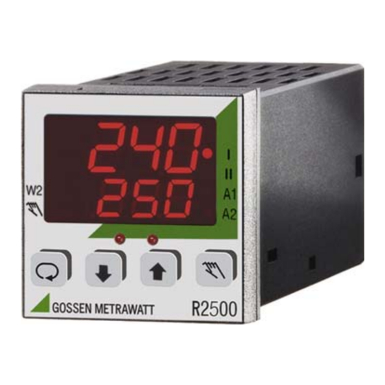
GMC-I Messtechnik GmbH R2500–10 Operation Figure 3: Controls Actual value Switching output for heating active Setpoint / heating current / Switching output for cooling active manipulating factor (operating level) Setpoint 2 active Alarm 1 active Alarm 2 active Manual operation... -
Page 11: Disabling Modifications
However, self-tuning can always be started via infrared or bus interface! Performance After Activating Auxiliary Voltage LED Segment Test Designations Actual Value Approx. 1.5 s Approx. 1.5 s Approx. 1.5 s Firmware Version Setpoint or oFF GMC-I Messtechnik GmbH R2500–11... -
Page 12: Operating Flow Chart
GMC-I Messtechnik GmbH R2500–12 Operating Flow Chart Operating Level Automatic Operation Actual Actual Actual Actual Actual Setpoint Ht. Current Man. Factor Setpoint can only be With heat current With program set here monitoring only controller only Program Controller Parameter Level... -
Page 13: Automatic Operation / Off
– Step-action If the key is configured to controller: The switching outputs can be adjusted directly with “more” or manual / automatic “less” by pressing the up and down scroll keys. GMC-I Messtechnik GmbH R2500–13... - Page 14 GMC-I Messtechnik GmbH R2500–14 Configuration press and hold simultaneously Configuration Display Selection Standard Comment tYP. j Sensor type Types J tYP. L tYP. K tYP. b tYP. S tYP. r tYP. n tYP. E tYP. t SEnS Type J tYP. v Not with standard signal tYP.
- Page 15 FEF0 Feed-forward control configuration. StvP Start-up active booS Start boosting LoGG Data logger recording Dark Display darkl set2 Parameter set conversion baCk Backup function stat Binary input Binary input StAt dynamic, switching by key GMC-I Messtechnik GmbH R2500–15...
- Page 16 GMC-I Messtechnik GmbH R2500–16 Configuration Display Selection Standard Comment Controller 2 Controller 1 phlt Program pause prun Program running No function HEAt Heater, more heat with step-action controller 0ut1 CooL out1 switching output Cooling, more cooling HEAt See page 21...
- Page 17 Start self-tuning Enable / disable See page 37 ramp Setpoint ramp only for program step Setpoint staircase Setpoint staircases, configurable rAMP controller with SPuP, SPdn and t SP Stvp no / yes Actuation inactive See page 25 GMC-I Messtechnik GmbH R2500–17...
- Page 18 GMC-I Messtechnik GmbH R2500–18 Configuration Display Selection Standard Comment r260 DIN 19244 E same as R2600 r260 With bus interface only Modbus Prot Bus protocol r217 DIN 19244 E same as R0217 hbth HB-Therm bAUd 9. 6 / 19. 2...
-
Page 19: Controller Types
Actuating cycle time is used as a time constant for an additional input filter. This controller type is not intended for temperature regulation, because it does not demonstrate the dynamics required for control without overshooting. GMC-I Messtechnik GmbH R2500–19... -
Page 20: Conversion Of Parameter Sets
GMC-I Messtechnik GmbH R2500–20 Conversion of Parameter Sets If the binary input is configured to parameter set conversion (SEt2 ), parameter set 2 is loaded when the contact is closed, and paramter set 1 is loaded when the contact is open. The active configuration is overwritten in each case. The W2 LED lights up when parameter set 2 and/or 3 is active. -
Page 21: Configuring The Switching Outputs And The Continuous Output
If two relay outputs are required for the actuating signals, for example in the case of three-step or step-action control, the alarm outputs can be exchanged with the actuator outputs. The Out = XCh configuration (see page 16) exchanges the functions of out1 with A1 and out2 with A2. GMC-I Messtechnik GmbH R2500–21... -
Page 22: Actuator Output For Contactor
GMC-I Messtechnik GmbH R2500–22 Actuator Output for Contactor If, during ascertainment of control parameters (manual optimization or self-tuning), a cycle time results which is significantly shorter than advisable for the service life of the contactor, cycle time can be increased to the limit of system controllability by configuring the actuating outputs for contactor control (rELA = YES). -
Page 23: Setpoint Ramps
Periods can be selected within a range of 0.3 to 25 seconds, and the filter remains inactive for other setting values. Due to the fact that this suppression filter influences control dynamics, ascertainment of control parameters by means of self-tuning or manual optimization has to be performed while oscillation suppression is active. GMC-I Messtechnik GmbH R2500–23... -
Page 24: Adaptive Measured Value Correction
GMC-I Messtechnik GmbH R2500–24 Adaptive Measured Value Correction If a control loop is interfered with by periodic disturbance of the actual value, control can be improved by activating adaptive measured value correction. Periodic disturbance is thus suppressed, without impairing the controller’s ability to react to system deviations. Correction is adapted to the oscillation amplitude of the disturbance to this end, and only the mean value is forwarded to the controller. -
Page 25: Hot-Runner Control
If the currently valid setpoint is still so far beneath the start-up setpoint that the condition for ending actuation cannot be fulfilled, the start-up procedure continues indefinitely. In this case, control variable limiting by means of maximum manipulating factor would be advisable. GMC-I Messtechnik GmbH R2500–25... -
Page 26: Feed-Forward Control
GMC-I Messtechnik GmbH R2500–26 Temporary Setpoint Increase (boosting) Temporarily increasing the setpoint in the hot-runner control mode can be used to free clogged mold nozzles of “frozen” material remnants. This procedure is triggered by bit 3 of the controller function, which is set via the interface, keyboard or the binary input. The binary input must be con- figured as follows to this end: In1 = booS. -
Page 27: Parameters Configuration
Read-out cycle time 0.1 ... 300 s Motor run-time 1 ... 600 s 60 s Only with step-action controllers hyst Switching hysteresis 0 ... MRS/2 For limit value monitoring and limit transducers GMC-I Messtechnik GmbH R2500–27... - Page 28 GMC-I Messtechnik GmbH R2500–28 Parameters Display Range Standard Comments sp H Maximum setpoint SP L ... X2 Limiting the setpoint entry SP L Minimum setpoint X1 ... SP H Maximum manipulating factor –100 ... 100% 100% Minimum manipulating factor –100 ... 100% –100%...
-
Page 29: Program Controller
The program can be started and stopped with a binary input: In1 = Prun. Wt.X Same as for run.X. If “wait until setpoint is reached” has been selected (with WAit = YES), the program waits until system deviation amounts to only 2° C before activating the next segment. GMC-I Messtechnik GmbH R2500–29... - Page 30 GMC-I Messtechnik GmbH R2500–30 hLt.X The running program has been halted, the momentary setpoint has been frozen (X stands for the current segment). The program can be halted with a binary input: In1 = PhLt. Control tracks Two control tracks can be activated for the duration of the segments. They can be assigned to available switching outputs with the setting: Out...
-
Page 31: Program Entry
If End is selected, no further entries are MS 2 Duration of segment 2 0:00 ... 99:59 displayed. SP 2 SP L ... SP H Target setpoint, segment 2 0°C tr 2 Control tracks, segment 2 ---- ... 21 ---- GMC-I Messtechnik GmbH R2500–31... - Page 32 GMC-I Messtechnik GmbH R2500–32 Configuration Display Selection Standard Comment MS12 End, 0:00 ... 99:59 Duration of segment 12 SP12 SP L ... SP H Target setpoint, segment 12 0°C tr12 Control tracks, segment 12 ---- ... 21 ---- Example: Desired temperature-time profile:...
-
Page 33: Manual Optimization
– Set dbnd to 0 in order to cause further overshooting with active switching output for cooling. Record two overshoots and two undershoots. – Record on-time T and off-time T for the last oscillation at the switching output for cooling or the continuous output. GMC-I Messtechnik GmbH R2500–33... - Page 34 GMC-I Messtechnik GmbH R2500–34 t dbnd = MRS dbnd = 0 (3-step and split range controllers only) x Evaluating the Start-Up Test – Apply a tangent to the curve at the intersection of the actual value and the setpoint, or the cut-off point of the output.
- Page 35 Pb II – Pb I – Pb I – Parameters 2-step controller 3-step controller Cont.-action controller Split range controller Step-action controller If either T or T is significantly greater than the other, value tu is too large. GMC-I Messtechnik GmbH R2500–35...
- Page 36 GMC-I Messtechnik GmbH R2500–36 Correction with manipulating factor limiting Y H positive:Pb I multiplied by 100 % / Y H Y H negative:Pb II multiplied by -100% / Y H Correction for step-action controllers in the event that T or T is smaller than tY: ...
-
Page 37: Self-Tuning
– If an error occurs during self-tuning, the controller no longer reads out an actuating signal. In this case, self-tuning must be aborted with the key. Additional information regarding error messages upon request. Self-tuning is enabled upon shipment from the factory (default setting). Starting the self-tuning function can be disabled in the configuration. GMC-I Messtechnik GmbH R2500–37... -
Page 38: Balancing
GMC-I Messtechnik GmbH R2500–38 Balancing Thermocouple Correction (parameter: CAL) The correction value is selected in C / F. The displayed correction value is added to the measured temperature. Cable Compensation for Pt 100 with 2-Wire Connection (parameter: CAL) Balancing is performed manually if the sensor temperature is known: CAL = known sensor temperature –... -
Page 39: Limit Value Monitoring
Quit AL display within 5 seconds with the key. – These errors can also be cleared with the binary input, if it has been configured to clear limit value errors (In 1 = quit). GMC-I Messtechnik GmbH R2500–39... -
Page 40: Heating Current Monitoring
GMC-I Messtechnik GmbH R2500–40 Heating Current Monitoring Current Measurement Heating current is acquired with an external transformer. Compatible with R2400 with GTZ 4121 for alternating and 3-phase current. Function An alarm is triggered if the current setpoint is fallen short of by more than 20% with activated heat (control output active), or if current is not “off”... -
Page 41: Heating Circuit Monitoring
– Error message LE appears after approximately 2 times tu, if heat remains on at 100% and measured temperature rise is too small. – Monitoring is not active: Where controller type = limit transducer, actuator or step-action controller During self-tuning With standard signal input (designation B2) Where manipulating factor limiting Y H < 20% GMC-I Messtechnik GmbH R2500–41... -
Page 42: Alarm History
GMC-I Messtechnik GmbH R2500–42 Alarm History • The alarm history includes 100 error status entries with the respective time stamps. Whenever at least one entire bit of the overall error status changes, the complete error status is saved with the current time stamp. -
Page 43: Error Messages
– sort: “actuator” or “limit transducer”). acknowledged (see below). Control outputs inactive, self-tuning must be aborted with Disturbance in self-tuning sequence in tune error 2 step 1 ... 9 (in this case step 2) keys. GMC-I Messtechnik GmbH R2500–43... -
Page 44: Error Acknowledgement
GMC-I Messtechnik GmbH R2500–44 Display Error Message Source Response Remedy Measured temperature rise is too small Control outputs inactive, error message remains until loop error with heat on at 100% acknowledged (see below). parameter error Parameter not within permissible limits Control outputs inactive, the parameter level is disabled. -
Page 45: Error Mask
Value Meaning Display default 0002 Heating current overrange 0004 Cold junction error 0010 Heating current not off Blinks 0020 Heating current too low Blinks 0040 Heating current too high Blinks 0100 Memory error 0200 Parameter error GMC-I Messtechnik GmbH R2500–45... - Page 46 GMC-I Messtechnik GmbH R2500–46 Channel error mask (A1M1 and A2M1) Wert Meaning Display default 0001 Broken sensor, 2 input SE H 0002 Reversed polarity, 2 input SE L 0004 Analog error 0008 Broken sensor SE H 0010 Reversed polarity SE L...
-
Page 47: Replacing An R2400 Controller With An R2500 Controller
20 to 15 • When configured as a step-action controller (R2400, features A2, A4), the configuration of the corresponding output is not Outx = CooL in the case of the R2500, but rather Outx = HcLo. GMC-I Messtechnik GmbH R2500–47... - Page 48 If both actuating signals are read out via relay, the relay connections must be changed (see table on page 47). Converting Parameters In the case of the R2500, the proportional bands are specified in the unit of measure of the controlled variable, instead of as a percentage of the...
-
Page 49: Technical Data
A1 and A2 Switching capacity 250 V AC/DC, 2 A, 500 VA / 50 W > 5 10 Service life switching cycles at nominal load Utilize external RC element (100 - 47 nF) at Interference suppression contactor GMC-I Messtechnik GmbH R2500–49... -
Page 50: Compactconfig Configuration Tool
The Z250I IR adapter is required in order to use the configuration tool. Further information regarding accessories and the latest version of the software, which can be downloaded free of charge, are available on the Internet at: http://www.gossenmetrawatt.com ( Products Controllers Compact Controller R2500) - Page 51 GMC-I Messtechnik GmbH R2500–51...
- Page 52 Edited in Germany • Subject to change without notice • PDF version available on the Internet Phone +49 911 8602-111 GMC-I Messtechnik GmbH +49 911 8602-777 Südwestpark 15 E-Mail info@gossenmetrawatt.com 90449 Nürnberg • Germany www.gossenmetrawatt.com...
Need help?
Do you have a question about the R2500 and is the answer not in the manual?
Questions and answers