
Subscribe to Our Youtube Channel
Summary of Contents for ControlByWeb WebRelay Wireless XW-210I
- Page 2 The XW-210 can be a self-contained wireless access point that requires no additional servers or ControlByWeb devices. In this mode the XW-210 provides live, real-time temperatures or input status directly to a single user through web browsers or the CBW Mobile app.
- Page 3 ➢ Powered from a 9 to 24V DC power adapter. The power supply voltage is monitored internally and can be logged. ➢ Sensor/Input status can control a relay on other ControlByWeb devices. ➢ Configurable logging of the input, counter, temperature, humidity, relay state and Vin.
- Page 4 Introduction XW-210 WiFi™ Users Manual 1.2 Part Numbers and Accessories Device Description Part Number Wi-Fi WebRelay with built-in web server XW-210I XW-210 Digital temperature sensor with short wire leads X-DTS-U Temperature Sensor (connects directly to the terminal strip) Digital temperature sensor with 3 foot wire leads X-DTS-S3C Temperature Sensor (housed in water resistant stainless steel probe)
- Page 5 XW-210 WiFi™ Users Manual 1.3 Wireless Communication Notes Due to the nature of wireless communications, transmission and reception of data can not be guaranteed. Data may be delayed, have errors, or be lost. Although delays or losses of data are rare with a well constructed network, data can be lost due to interference, noise, reflections, or other environmental conditions.
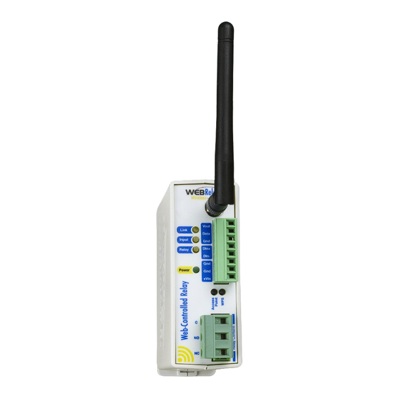
- Page 6 Introduction XW-210 WiFi™ Users Manual 1.5 Connectors & Indicators Relay The XW-210 has an internal high-current relay. Screw terminals are provided for the Common, Normally Open, and Normally Closed contacts of the relay. The screw terminals are internally connected directly to the relay with no internal fuse or other over-current protection.
- Page 7 XW-210 WiFi™ Users Manual The XW-210 has an 8-position removable screw terminal connector for power, input and sensor connections. A separate 3-pin connector provides connections to the internal relay. 8-Pin Connector Terminal Description Vout +5V output to power 1-wire sensor(s), 50mA max Serial data line for 1-wire sensor(s) Data Gnd output for 1-wire sensor(s)
- Page 8 Introduction XW-210 WiFi™ Users Manual 1.6 Accessing the XW-210 using a Web Browser The XW-210 has a built-in web server that provides simple web pages that can be accessed directly using a standard web browser. This allows users to access the unit with NO SPECIAL SOFTWARE installed on their computer.
-
Page 9: Installation Guidelines
XW-210 WiFi™ Users Manual Section 2: Installation and Connections Installation consists of mounting the XW-210 and connecting it to a power source. See Section 3: Provisioning for instructions on commissioning the XW-210 such that it can recognize and connect to your Wi-Fi access point. - Page 10 Installation and Connections XW-210 WiFi™ Users Manual 2.2 Making Connections CAUTION: Make sure the power is shut off before making connections CAUTION: This unit should be installed by a qualified technician. CAUTION: Miswiring or misconfiguration could cause permanent damage to the XW-210, the equipment to which it is connected, or both.
- Page 11 XW-210 WiFi™ Users Manual 2.2.2 Antenna Connection The XW-210 comes with an approved 2.4GHz omnidirectional antenna for use with WLAN devices using WiFi (802.11b/g/n). The omnidirectional pattern is suitable for point-to-multipoint broadcasting in all directions. Connect the antenna to the Reverse SMA connector on the faceplate. Do not operate the XW- 210 without the antenna connected.
- Page 12 Installation and Connections XW-210 WiFi™ Users Manual 2.3 Relay Connections (Control a device over an IP network) The illustration below shows a simple example of using the relay in the XW-210 to control a device over an IP network. The device to be controlled is wired in series with the relay contacts. Note: The circuit must include a fuse or circuit breaker to provide over-current protection.
- Page 13 XW-210 WiFi™ Users Manual 2.4 1-Wire Sensor Connections The XW-210 has a “1-wire” port which supports up to four digital temperature or other Xytronix 1-wire sensors. The sensors share the same three connections for communications and power (+5V, Ground, Data). Every sensor on the bus is assigned a unique serial number when it is manufactured. That number is used to address the sensor during communication.
- Page 14 Installation and Connections XW-210 WiFi™ Users Manual Multiple sensors can be connected in two ways: directly connected (star topology) or “daisy chained” (linear topology). Many factors can determine the maximum length of the cable, including the sensor network topology, the type of cable used, the number of sensors and ambient electromagnetic noise. Combined cable lengths to all sensors of 600 ft using Cat 5e cable have been successful.
- Page 15 XW-210 WiFi™ Users Manual 2.5 Digital Input Connections The XW-210 has an optically-isolated digital input which can be used to control the relay and/or a remote relay (over the network), or simply to monitor the state of a device. To use this input, connect a DC control voltage directly to the input, and customize the input function using the XW-210 configuration pages.
- Page 16 Installation and Connections XW-210 WiFi™ Users Manual 2.5.2 Switch Closure Connections The XW-210 can sense the state of a switch closure sensor. Sensors with switch closure outputs include push buttons, magnetic door alarm switches, micro-switches, or any device which has a relay, switch closure or open collector output.
- Page 17 XW-210 WiFi™ Users Manual 2.5.3 Water Leak Sensor Connections A GRI-2605 water leak detector can be directly connected to the XW-210. The sensor detects the presence of water or other conductive liquids. The sensor has 4-wires which are connected as shown below.
- Page 18 Installation and Connections XW-210 WiFi™ Users Manual 2.5.4 AC Input Connections If an AC signal voltage needs to be detected, use a signal conditioner to convert the AC signal to a DC voltage within the input range. An AC signal conditioner can be made using a diode (or bridge rectifier) and a capacitor.
- Page 19 XW-210 WiFi™ Users Manual Section 3: Provisioning After making the sensor connections and providing power, you must provision the XW-210 for use on your wireless network. The goal is to configure the XW-210 such that it can recognize and attach to your Wi-Fi access point.
- Page 20 Provisioning XW-210 WiFi™ Users Manual WPS (Wi-Fi Protected Setup) The WPS Push button method, provides a simple method for attaching the XW-210 to a wireless network without needing to use any setup pages. Although using this method to connect the XW-210 to the network is simple, you will not be able to access the XW-210 web server unless you know the IP address that was assigned by the DHCP sever (router) or unless mDNS services are available on your device.
-
Page 21: Application Examples
XW-210 WiFi™ Users Manual 3.3 Application Examples The XW-210 can be configured for many different applications. Two general examples are described below: 3.3.1 Warehouse Temperature Example with no Access Point You wish to monitor the temperature of a warehouse with a your smart phone. You don't have a WiFi access point. - Page 22 Web Server XW-210 WiFi™ Users Manual Section 4: Web Server The internal web server presents two classes of web pages; Setup pages and Control pages. Setup pages are used by an installer to provision and configure the XW-210. The Control page allows the relay to be controlled and displays temperature and digital input status information.
- Page 23 XW-210 WiFi™ Users Manual Temperature Units: This global setting selects temperature units of either Fahrenheit and Celsius. All settings entered and displayed on subsequent pages will be in the units selected. Part Number: This is the full model number of the XW-210. Firmware Revision: This is the current revision of the internal software.
- Page 24 Web Server XW-210 WiFi™ Users Manual 4.2 WiFi Networks Tab As a Wi-Fi client device, the XW-210 attempts to automatically connect to configured Wi-Fi access points. The settings on this page are used to configure this process. WiFi SETTINGS SSID: The SSID (Service Set Identifier) is the name of the Wi-Fi network you wish the XW-210 to connect to.
- Page 25 XW-210 WiFi™ Users Manual Type of authentication used by the access point for connections. Security Key: Enter the security key or password for the WiFi network to connect to (hidden when not applicable.) IP SETTINGS Use DHCP: This option allows DHCP to be enabled or disabled. If this option is set to Yes, the XW-210 will wait for an IP address from a DHCP server each time it is powered.
- Page 26 The format is entirely dependent upon the server requirements. This field can be up to 80 characters long. Default text is provided only as an example placeholder. The default text is [<Serial Number>]:ControlByWeb,XW-210. Connection Interval: This field specifies the periodic interval in which XW-210 attempts to connect to the remote server, or if XW-210 is already connected, it is the interval in which XW-210 sends the connection string.
- Page 27 This can be used in an environment where a web server on the Internet provides a custom web page to XW-210 and other ControlByWeb products. Users access the XW-210 through the web server rather than communicating directly with it. This method is sometimes referred to as “web services” and allows programmers to create powerful, custom web pages to multiple devices using the web programming languages of their choice.
- Page 28 Web Server XW-210 WiFi™ Users Manual know the IP address of XW-210. This means that XW-210 can get its IP address dynamically from a DHCP server, simplifying the installation. Second, since the connection from XW-210 is outgoing, rather than incoming, the local router on the network where XW-210 resides doesn't need to be configured to forward sockets.
- Page 29 XW-210 WiFi™ Users Manual EMAIL SETTINGS An email can be sent when a temperature alarm or digital event occur. A BASIC script can also initiate an email message. This section is used to configure the email settings for up to eight email addresses. The same message is sent to each email address.
- Page 30 Web Server XW-210 WiFi™ Users Manual Email 7: When an alert occurs an email message is sent to this address. Email 8: When an alert occurs an email message is sent to this address. Email Content: When “Full State” is selected, all visible fields in the control page will be included in the email message to be sent out.
- Page 31 XW-210 WiFi™ Users Manual and the XW-210 is not connected to the Internet. In this mode, no email messages can be sent and the Test Email button is disabled. Xytronix Research & Design, Inc. Page 31...
- Page 32 Web Server XW-210 WiFi™ Users Manual 4.3 Password Tab The XW-210 has separate passwords for the Setup and Control pages. The passwords can be changed on this page. The username (admin) is fixed and cannot be changed. SETUP PAGE Setup Password: The Setup Password, which is required to access the setup pages, can be modified by entering a new password here.
- Page 33 XW-210 WiFi™ Users Manual 4.4 Date/Time Tab XW-210 uses the time of day for logging (a time stamp is included with each logged event.) The time is stored and displayed in 24-hour time format. The XW-210 does not have an event scheduler. The time in the XW-210 is not battery backed and will be lost if the device loses power.
- Page 34 Web Server XW-210 WiFi™ Users Manual SYNC WITH NPT SERVER Server Name/IP Address This field is used to specify the name or IP address of the NTP server. If a name is specified, a working DNS server address must be entered into the Network settings. If the IP address is specified, it should be entered in the following format aaa.bbb.ccc.ddd where each of the letters represents a number between 0 and 255.
- Page 35 XW-210 WiFi™ Users Manual 0.south-america.pool.ntp.org 1.south-america.pool.ntp.org 2.south-america.pool.ntp.org 3.south-america.pool.ntp.org Africa (http://www.pool.ntp.org/zone/africa): 1.africa.pool.ntp.org 1.pool.ntp.org 3.pool.ntp.org Sync With Server This option allows the user to specify how often the time on XW-210 will be synchronized with the time server. When the submit button on this page is pressed, XW-210 will immediately synchronize with the time server.
- Page 36 Web Server XW-210 WiFi™ Users Manual DAYLIGHT SAVINGS Daylight Savings Enabled: In many parts of the United States and in some other countries, the time is shifted forward by one hour during the summer months. This is an effort to conserve energy by making the daylight last longer into the evening hours.
- Page 37 XW-210 WiFi™ Users Manual 4.5 Logging Tab XW-210 can be configured to record data such as sensor data and changes in I/O state. Both periodic and event-based logging are supported. The logged data is stored in internal nonvolatile memory and can be retrieved by entering the command http://{XW-210 IP address}/log.txt.
- Page 38 Web Server XW-210 WiFi™ Users Manual Logging Rate: This field is used to specify the time period of logging. A numerical value is entered into the text field, and the unit of time is selected using the adjacent radio buttons. The range of values in this field is 1-20864. Time units are Minutes, Hours, and Days.
- Page 39 XW-210 WiFi™ Users Manual 4.6 Input Tab These settings determine how the XW-210 processes the digital input. The digital input has a counter which counts the number of input pulses. The input has a set debounce of 20ms before counters or events are processed.
- Page 40 Web Server XW-210 WiFi™ Users Manual Off Status Color: This field specifies the color that will be displayed on the Control Page when the input is considered Off. Options are Green, Red, Yellow, Blue and Grey. Counter Options This settings determines what triggers the counter to increment. The default setting for this field is: “Counter off”.
- Page 41 XW-210 WiFi™ Users Manual server must be defined. When an Email address is entered via the WiFi Networks tab, the check boxes will show the respective Email addresses. Remote Service: When this box “Send State Message on Input Change” is checked, State messages will be sent whenever the input state changes.
- Page 42 Web Server XW-210 WiFi™ Users Manual 4.7 Relay Tab Description This text field is used to describe the function of the relay. The text appears to the left of the corresponding relay status on the Control Page and in the email message when email alerts are enabled. Up to 24 characters may be entered in this field.
- Page 43 XW-210 WiFi™ Users Manual Page. Up to 15 characters may be entered in this field. The default text is “PULSE”. On Status Text The text in this field specifies the text that will be displayed in the Control Page and in email messages when the relay is On.
- Page 44 Web Server XW-210 WiFi™ Users Manual the relay is on. Latch relay on when input [on, off, changes] (reset via web): The relay latches on when the input is [on, off, changes] Latch relay off when input [on, off, changes] (reset via web): The relay latches off when the input is [on, off, changes] Toggle relay when input [on, off, changes]: The relay changes state when the input is [on, off, changes]...
- Page 45 Remote Services must be enabled and properly configured for this feature to be effective. The digital input can be configured to control the relay contacts of another ControlByWeb™ device (such as WebRelay™) at a remote location. The ‘Remote Service Options’ setting is used to specify if and how the input affects the remote relay.
- Page 46 Web Server XW-210 WiFi™ Users Manual command is sent to the remote device to pulse the relay. If Relay is selected the following Action options are available: Remote command equals relay: When the local relay is on, a command is sent to the remote device to set the relay state to on.
- Page 47 XW-210 WiFi™ Users Manual 4.8 Sensor Tab Up to four temperature or other Xytronix 1-wire sensors can be connected to XW-210. Each of the1-wire sensors have specific settings. The settings for the first 2 sensors are shown below. Sensor Description: This text will appear in email messages when email alerts are enabled as well as to the left of the corresponding temperature/humidity value on the Control Page.
- Page 48 Web Server XW-210 WiFi™ Users Manual sensor from the drop-down list. Selecting sensors is simplest when the sensors are connected to the bus one at a time. The procedure is to start with one sensor and associate it with the appropriate sensor number by selecting the sensor address within the appropriate drop-down list.
- Page 49 Email addresses. Remote Services: The XW-210 can be configured to send messages to other ControlByWeb™ products that are located at a remote location on the network. This field specifies the action taken due to a temperature alarm condition.
- Page 50 Web Server XW-210 WiFi™ Users Manual 4.9 Script Tab The XW-210 can run custom programs written in a simplified version of BASIC. This page is used to load and execute these programs. Before it can be loaded to the XW-210, a script must first be prepared as a .txt file.
- Page 51 XW-210 WiFi™ Users Manual 4.9.1 Example Script The following is an example script which monitors a door switch. An alarm sounds after a door has been open for 10 seconds and turns off if the door is closed. It includes a trigger to exit the timer if the input turns off before 10 seconds has elapsed.
- Page 52 Web Server XW-210 WiFi™ Users Manual 4.10 Control Page and Register Setup Tab The Control Page Setup page is used to set parameters that affect the view of the Control Page, including what measurement values and buttons are to be shown. Module Description The text entered here appears at the top of the Control Page.
- Page 53 XW-210 WiFi™ Users Manual Refresh rate: How often the Control Page status is updated. The default value is 3 seconds. Display Configuration These check boxes select which input/output resource is displayed on the control page. Each check box determines whether or not the status of the resource is displayed. Relay: Determines if the relay status and/or what buttons are visible on the control page.
- Page 54 Control Page XW-210 WiFi™ Users Manual Section 5: Control Page The relay, digital input and temperature sensors can be monitored and controlled using a web browser, by sending text commands to an XML status/control page, and/or by sending Modbus/TCP requests. 5.1 Browser Operation Once the XW-210 is set up, users can access the Control Page using a web browser.
- Page 55 XW-210 WiFi™ Users Manual Header Displays the text entered in the Module Description Text field on the Control Page Setup tab in the setup pages. This is usually a description of the application such as “2nd Floor Freezer”. Input This row displays the current state of the digital input. The text in the left column (by default reads “Input 1”) is specified in the description field of the Input tab in the setup pages.
- Page 56 Control Page XW-210 WiFi™ Users Manual 5.2 Control Page Tab The second method of accessing the control page is through the setup pages (http://192.168.1.2/setup.html). Clicking the Control Page Tab will open a new browser window and display the control page shown below. To access the setup tabs again, click on the XW-210 Setup tab in your browser to return to the previous browser window.
- Page 57 XW-210 WiFi™ Users Manual Section 6: Auxiliary Operations 6.1 XML Custom XML computer applications may be created to monitor and control the XW-210. This method does not use a web browser. There is a single XML page that can be used to monitor and control the XW-210, state.xml.
- Page 58 Auxiliary Operations XW-210 WiFi™ Users Manual XML Tags* Monitor Values <sensorX> x.x = Indicates that no sensor reading is available 77.3 = Current sensor reading <sXAlarm> Current state of the sensor alarms 0 = Normal 1 = Alarm 1 2 = Alarm 2 <count1>...
- Page 59 XW-210 WiFi™ Users Manual 6.1.3 Message Acknowledgment By default, when commands are sent to XW-210, the state.xml page is returned. The xml reply can be disabled by adding the noReply field as follows: Command Description state.xml?relay1State=1&noReply=1 Turn Relay 1 ON without returning state state.xml?relay1State=0&noReply=1 Turn Relay 1 OFF without returning state Xytronix Research &...
- Page 60 Authorization: Basic bm9uZTp3ZWJyZWxheQ==\r\n\r\n bm9uZTp3ZWJyZWxheQ== is the Base64 encoded version of the user “name:password,” none:webrelay. A utility is provided at http://www.controlbyweb.com/encoder to encode the password. Simply type the string username:password into the website and press 'Encode'. cURL Example The following is an html request without a password: curl "http://192.168.1.2/state.xml?relay1State=1"...
- Page 61 An external web server can integrate multiple ControlByWeb products into a single control page. In other words, the user may not be aware that he/she is using multiple ControlByWeb™ devices, but rather the user sees an integrated control page for the entire system. In addition, the use of an external web server...
- Page 62 Auxiliary Operations XW-210 WiFi™ Users Manual means that the XW-210 can be installed using DHCP. In addition, no special router configuration is required. This makes the network installation of the XW-210 very simple, and since no incoming ports need to be opened in the router, security is not compromised. See Section 4.2: WiFi Networks Tab for more information.
- Page 63 XW-210 WiFi™ Users Manual 6.4 Email Notification 6.4.1 Email Notification Description XW-210 can be configured to send messages to eight email addresses when certain events occur. Events that can trigger email messages include relay/input state changes and temperature/humidity changes. When an email message is sent, it looks similar to this: XW-210 Trigger: Relay 1 ON Relay 1: ON...
- Page 64 Auxiliary Operations XW-210 WiFi™ Users Manual 6.4.2 Email Notification Setup Email notification requires that the following fields are properly configured. See Section 4.2: WiFi Networks Tab for a description of each field. WiFi Networks Tab IP Address Subnet Mask Gateway Preferred DNS Server (this is required if Mail Server is entered by name and not by IP address) SMTP Server SMTP Server Port...
- Page 65 XW-210 WiFi™ Users Manual LogFile XW-210 logs information to log.txt. This log file is a text file stored in nonvolatile memory and will not be lost due to power failure. The log files are stored in a circular buffer which writes from the beginning of the allocated memory space to the end and then repeats from the beginning (over-writing the original data).
- Page 66 Auxiliary Operations XW-210 WiFi™ Users Manual the default IP address, and port 8000, the log file would be read as follows: http://192.168.1.2:8000/log.txt The log.txt file may be erased with the following command: http://192.168.1.2/log.txt?erase=1 After erasing the file, it might be necessary to refresh the page. Note: If the Control Password is enabled in the setup pages, the password will be required to access the log file.
- Page 67 XW-210 WiFi™ Users Manual 6.6 Modbus/TCP XW-210 can be controlled and monitored using Modbus/TCP protocol. This provides a standard means of using XW-210 with devices and software from other manufacturers. This section is not a tutorial on Modbus and it is assumed that the reader is already familiar with Modbus. Detailed Modbus information can be found at http://www.modbus.org.
- Page 68 Auxiliary Operations XW-210 WiFi™ Users Manual 6.6.2 PLC Device Addressing There are generally two schemes for accessing Modbus devices. The first is by specifying the Modbus function code, memory type, and address. The second, sometimes called PLC addressing, requires only the address.
- Page 69 XW-210 WiFi™ Users Manual 6.6.3 XW-210 Full Address Table The table below gives commonly used function codes, memory types, data sizes, and equivalent PLC addresses for accessing the XW-210. The data size will be the same regardless of the addressing mode. Function Address Data Size...
- Page 70 Auxiliary Operations XW-210 WiFi™ Users Manual 6.6.4 Read Coils - Modbus Function Code 01 (0x01) Read the state of the relay. Request Start Address: 0x0000 (coil 1) Coil Quantity: 0x0001 (1 coil) Response The XW-210 will respond to the request with a data field of one byte, each bit representing the coil status.
- Page 71 XW-210 WiFi™ Users Manual 6.6.5 Read Discrete Inputs – Modbus Function Code 02 (0x02) This function returns the state of the digital input. Request Start Address: 0x0000 (input1) Input Quantity: 0x0001 The sum of the starting address and the quantity of coils must not be greater than 0x0001. Response The input state is indicated by bit zero of the status byte.
- Page 72 Auxiliary Operations XW-210 WiFi™ Users Manual 6.6.6 Read Sensors – Modbus Function Code 03 (0x03) The Read Holding Registers function is used for the temperature and other Xytronix 1-wire sensors. Request 32-bit sensor values are read from 16-bit register pairs. Consequently, senors addresses and registers must be even numbers.
- Page 73 XW-210 WiFi™ Users Manual 6.6.7 Write Single Coil Modbus Function Code 05 (0x05) – Relays may be controlled one at a time. Request Start Address (2 bytes): 0x0000 (Relay 1) Output Value (1 byte): 0x00 (OFF), 0xFF(ON) Padding (1 byte): 0x00 Response The response mirrors the requested state, 0x00 or 0xFF.
- Page 74 Auxiliary Operations XW-210 WiFi™ Users Manual 6.6.8 Write Multiple Coils - Modbus Function Code 15 (0x0F) One byte can be written to set the state of all relays, each bit representing one relay. Request Relay states are controlled by specifying the start address of the first relay to be controlled, the count of the relays to be affected, and the relay state byte.
- Page 75 XW-210 WiFi™ Users Manual 6.6.9 Write Multiple Registers – Modbus Function Code 16 (0x10) The Modbus Write Multiple Registers function can be used to pulse the relays. Request The Modbus Write Multiple Registers function is used to pulse the relay(s) for a specified time. When the XW-210 receives this command, it immediately turns the appropriate relay(s) ON (if not already on) and starts the pulse timer.
- Page 76 Some non-standard commands have been added, and some commands may function differently on the XW-210 BASIC interpreter than on other platforms. The following is a short tutorial on the supported BASIC functions. Example scripts are available at www.controlbyweb.com. Contact customer support if further assistance is required. 6.7.1 Structure A BASIC script is written as a .txt file, which is then uploaded to the device using the Script setup tab.
- Page 77 XW-210 WiFi™ Users Manual 6.7.3 Supported Statements The following are the statements supported by the ControlByWeb™ BASIC interpreter. The LET statement assigns a variable a value. The format is: LET (variable) = (expression) IF THEN, ELSE, END IF The IF THEN statement tests the truth of a condition. The ELSE statement defines a second function if the condition is found false.
- Page 78 Auxiliary Operations XW-210 WiFi™ Users Manual EMAIL The EMAIL statement causes the device to send an email of the same format as that generated by other status change and alarm conditions. The event that triggered the email is given, followed by the I/O or Sensor that you want to email.
- Page 79 XW-210 WiFi™ Users Manual 6.7.4 User-Defined Variables Two types of variables are available for use in the ControlByWeb™ BASIC interpreter, user-defined variables, and predefined variables. Up to 10 user variables may be initialized. These must be single character, lower case letters.
- Page 80 Auxiliary Operations XW-210 WiFi™ Users Manual 6.7.5.3 Input Variables The digital input states can be read in BASIC scripts. input1 'digital input 1 Example: Let a = input1 'sets 'a' equal to value of input 1 6.7.5.4 Counter Variables The input counter can be read in BASIC scripts. count1 'input 1 counter Example:...
- Page 81 XW-210 WiFi™ Users Manual 6.7.5.8 Event Variables Data and time variables can be used to execute script events. Up to five date variables are available. 'event date variable 1 … 'ed2, ed3, ed4 'event date variable 5 The value assigned to event variables should be in the format mm/dd/yyyy. The event date variables store the number of days that have passed since January 1, 1970.
- Page 82 6.7.7 Testing and Debugging A copy of the BASIC interpreter for Windows is available on www.controlbyweb.com for testing and debugging. The XW-210 will only acknowledge errors as it runs. This means that if a path of the script is not encountered, errors may still exist.
- Page 83 The network discovery protocol listens for specific requests on UDP port 65431 sent to the IP broadcast address 255.255.255.255. All requests must have the proper header and, when applicable, the correct MAC address. This header is the first 12 bytes of all messages and is simply the string 'ControlByWeb'. Header...
- Page 84 The only way to re-enable this request, is to reset the device to factory defaults, or re-associate the device to a WiFi network via WPS. Request: Header (12 bytes) ASCII String ControlByWeb Message ID (1 byte) Setup Information request 0x03 -or- 0x06 MAC Address (6 bytes)
- Page 85 XW-210 WiFi™ Users Manual Successful Response: Header (12 bytes) ASCII String ControlByWeb Message ID (1 byte) Setup successful response 0x04 MAC Address (6 bytes) Binary version 0x00 0x0c 0xc8 0x00 0x00 0x00 Error Response: Header (12 bytes) ASCII String ControlByWeb...
- Page 86 WPS: Yes, push button activated (Wi-Fi Protected Setup) Connectivity: Always connected Remote Server: ControlByWeb's X-600™ or cloud-based server Remote Relays: Control relays on other ControlByWeb™ products Polling: state.xml (web-server is always active) Power Requirements Input Voltage: 9-28 VDC Current: See table below for typical values at 25°C...
- Page 87 Works with digital “1-wire” thermometer probes Interchangeable, no calibration needed Dallas Semiconductor DS18B20 digital 1-wire thermometer Available in bare or encapsulated versions Also works with ControlByWeb™ wall-mount humidity sensors and other Xytronix 1-wire sensors. Measurement Range: -55°C-to 125°C (-67°F to 257°F) Accuracy: +/-0.5°C from -10°C to +85°C.
- Page 88 Appendix A: Specifications XW-210 WiFi™ Users Manual Logging Stored in non-volatile flash memory Circular buffer 512-Kbytes (16000 to 32512 log entries depending on configuration) Scripts Implement special or custom features with a BASIC script Max size 4-Kbytes Environmental Indoor use or NEMA-4 protected location Altitude: up to 2000m Operating Temperature:...
- Page 89 Appendix B: Trademark and Copyright Information This document is Copyright ©2016 by Xytronix Research & Design, Inc. All rights reserved. XW-210™, WebRelay™, ControlByWeb™, and Xytronix Research & Design™ are trademarks of Xytronix Research & Design™, Inc. 2005-2017. All other trademarks are the property of their respective owners.
- Page 90 For warranty service or repair, customer must contact Xytronix Research & Design, Inc. technical support (support@ControlByWeb.com) and obtain a Return Authorization number (RA#). Before issuing an RA#, a support technician will work with customer to try to resolve the issue without returning the product. If technician determines that product must be returned for service an RA# will be issued.
- Page 91 XW-210 WiFi™ Users Manual Appendix D: FCC Statement This device complies with Part 15 of the FCC Rules. Operation is subject to the following two conditions: 1. This device may not cause harmful interference. 2. This device must accept any interference received, including interference that may cause undesired operation.
- Page 92 Appendix E: Mechanical Dimensions XW-210 WiFi™ Users Manual Appendix E: Mechanical Dimensions Page 92 Xytronix Research & Design, Inc.
Need help?
Do you have a question about the WebRelay Wireless XW-210I and is the answer not in the manual?
Questions and answers