Table of Contents
Advertisement
Advertisement
Table of Contents

Summary of Contents for Permaquip Ironman
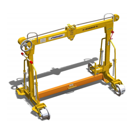
- Page 1 Operating & Maintenance Manual Ironman (Standard and LUL) Permaquip Ltd Brierley Industrial Park, Stanton Hill, Sutton-in-Ashfield Nottinghamshire, NG17 3JZ Tel: +44 (0) 1623 513349 Fax: +44 (0) 1623 517742 E-mail: sales@permaquip.co.uk www.permaquip.co.uk MAN-M-O-105_19 26/02/2016 Page 1 of 44...
-
Page 2: Table Of Contents
Issue and Revision Record ................4 Introduction ..................... 5 Safe and Correct Use ..................6 Technical Specification ..................8 Physical Data for Ironman Assembled ............8 Mass Data for Components ............... 8 Physical Data for Sleeper Lifting Attachments ........... 8 Load Specifications ................... 9 Operational Limits ................... - Page 3 Whilst Permaquip Limited has taken every care in preparing this User Guide it is intended as a technical guideline only. Save to the extent that there are statutory rights to the contrary, Permaquip accepts no liability in relation to any use or reliance made of any information in this User Guide.
-
Page 4: Issue And Revision Record
1 ISSUE AND REVISION RECORD This document will be updated when necessary by the re-issue of the complete document. Revised Revised Issue Description Date Page No. Changes for new MD 31/12/2009 C.H. Maximum length was 300’, increased to 26/08/2011 M.J.K. 360’. -
Page 5: Introduction
(P&C) from one location to another. The Ironman can also be used to transpose rail from one side of the track to the other. Therefore by straddling the running rails, access to the four-foot, six-foot and cess is possible. -
Page 6: Safe And Correct Use
3 SAFE AND CORRECT USE Please keep this User Guide for future reference. To ensure safe and correct use of the Ironman the following should be noted: Wear eye, feet, head and hand protection when using the Ironman. Additional Personal Protective Equipment (PPE) should be worn according to local regulations. - Page 7 For transposing operations ensure the Ironman is on stable and firm ground and level within the 150mm MAXIMUM on track operating cant, failure to do so may result in injury. Do not attempt to move the Ironman when under transposing conditions.
-
Page 8: Technical Specification
4 TECHNICAL SPECIFICATION Physical Data for Ironman Assembled Standard Assembly LUL Assembly Width 1935 mm 1935 mm Depth 1085 mm 1065 mm Height 1410 mm 1400 mm Total Mass 153.5 kg 141.5 kg Centre of mass Central Central Mass Data for Components... -
Page 9: Load Specifications
For LUL rail, using a Yale Pull-Lift, Adaptor Link, and Rail Lifting Clamp: SWL 1500 kg when lifting and during transportation For all rail types, using the Rail Storage Bracket mounted on the Ironman (in addition to the appropriate Rail Clamp): SWL 500 kg during storage only 2. -
Page 10: Operational Limits
Uncertainty is 50% of the values stated. Product Compliance The standard Ironman complies with RIS-1701-PLT. The Ironman also complies with the following: • Directive 2006/42/EC Safety of Machinery. • Directive 93/68/EEC CE Marking. - Page 11 MAN-M-O-105_19 26/02/2016 Page 11 of 44...
- Page 12 MAN-M-O-105_19 26/02/2016 Page 12 of 44...
- Page 13 MAN-M-O-105_19 26/02/2016 Page 13 of 44...
-
Page 14: Storage And Transportation
5 STORAGE AND TRANSPORTATION Storage The Ironman and any associated spare parts should be stored in a dry and secure environment. Safety critical spare parts must be stored in a dry, secure and controlled environment. Transportation During transit the Ironman should be secured, and kept away from all electrified lines. -
Page 15: General Layout
6 GENERAL LAYOUT The following shows the main components of the Ironman before assembly (lifting gear not shown). The following outlines the main components once assembled. MAN-M-O-105_19 26/02/2016 Page 15 of 44... -
Page 16: Operating Instructions
2. It is recommended that the Ironman is assembled by a minimum of two persons. Once assembled it is recommended that it is lifted by four persons. 3. Check that all parts of the Ironman have the same serial number, the SWL is shown and the ‘Next Brake Test Due’ has not expired. - Page 17 6. On firm level ground or on track, stand one of the End Frame Assemblies vertically and locate the Top Beam Assembly in position as shown below. 7. Insert the Clamping Screw and tighten, as shown below. This secures the End Frame and Top Beam Assembly together.
- Page 18 8. Mount the Bottom Cross Beam onto both of the End Frame Assemblies, as shown below. 9. The Ironman is now assembled. The appropriate lifting equipment can now be hooked onto the Top Beam carriage, as shown below. If required, mount the Rail Storage Bracket onto the un-braked End Frame Assembly as shown below.
-
Page 19: Fitting The Red Lights
7.3 Fitting the red lights The Red Lights are located in two positions on the Ironman Top Beam. There are no additional fixings required as they slot into the Light Brackets fitted within the apertures, as shown below. The two locking screws supplied can be fitted to prevent unauthorised removal. -
Page 20: Moving The Assembled Ironman
It is designed to be lifted by four persons, as shown below. Once the Ironman is on the track ensure that all four wheels are in contact with the rail head. -
Page 21: Operating The Ironman
Ensure the operator’s hands and fingers are on the outside of the handwheel at all times. Before attempting to use the Ironman, the following checks must be made: 1. Check that the Carriage Traverse is working correctly; - Push in and rotate the handwheel. - Page 22 Rail Storage Bracket is mounted on the Un-braked Frame Leg of the Ironman. The removable pin locates in one of two positions. The outer position is used for flat-bottom rail, whereas the inner position is used for Bull-head rail.
- Page 23 7.5.2 Traversing Operations The following procedure outlines the correct method for operation. 1. Position each Ironman over the items to be lifted. 2. Manoeuvre the carriage. To do this grip the handwheel with both hands, push the handwheel to compress the spring and disengage the lock, turn the wheel approx.
- Page 24 Bottom Cross Beam. Ensure that some tension remains in the Lifting Tackle Assembly to retain the rail in position. The Ironman can now be pushed along the track and walking pace or slower to the required unloading site. The Ironman is manually propelled and must be attended by the correct amount of personnel to ensure full control is kept at all times.
- Page 25 The number of Ironman required will depend upon the total length of rail and profile being moved. The following information provides guidance on these figures based on 50kg/m rail: Rail length Min. Number of Max. Distance Maximum rail Ironmen between Ironmen overhang Up to 60’...
- Page 26 7.5’ overhang with 10’ overhang Switch Light Heavy Light Heavy Central Central Type N/R* Do not use Ironman as lifting capacity exceeded N/R* - In this lift case, the central Ironman is not required. MAN-M-O-105_19 26/02/2016 Page 26 of 44...
- Page 27 Remove the Single Leg Chain Assembly and replace it with the Rail Lifting Clamp. Replace the Lower Bolt in the Adaptor Link Assembly. The LUL Ironman is now ready for lifting rail. To convert between a Rail Lifting Clamp to a Single Leg Chain Assembly reverse the process outlined above.
-
Page 28: Using The Sleeper Lifting System Attachments
3. Attach the beam to both carriages using the pins at each end and lock in place with the lynch pin (see below). 4. Place one frame into the base of each Ironman so that all four pins are locked in place (see below) 5. -
Page 29: Defined Words
8 DEFINED WORDS The following outlines the defined words used within this Maintenance Programme. Term Action required Adjust Correct to defined limits Change Remove the original and fit a new or overhauled part or assembly in its place. Check Determine a particular nominated condition before, during or after repair, for example completeness, security, position Clean Remove all dirt and deposits... -
Page 30: Document Review
9 DOCUMENT REVIEW The following Maintenance Programme specified for the Ironman is reviewed as follows: 1. The Maintenance Programme is reviewed on an annual basis to investigate: • The potential for improvement. • The maintenance activities. • The Ironman performance and associated components. -
Page 31: Maintenance
10 MAINTENANCE The following Maintenance Programme specified for the Ironman is as follows: In order to carry out this Maintenance Programme in a manner that achieves the required safety and quality, the following minimum level of competence is required: a) For all activities the person leading the task must be able to follow and carry out the instruction detailed in this document. -
Page 32: General
Note that: • The Maintenance and Testing of the Brakes, Wheels and Axles are defined as Railway Safety Critical under CoP0010, Railway Safety Critical Maintenance Elements of Small Plant and Equipment. • The Maintenance and Testing of the Brakes are covered under CoP0018, Rail Mounted Manually Propelled Equipment. - Page 33 Product folder. Do not record information directly onto this document. For spare parts please contact your nearest Permaquip service centre. It is recommended that parts are purchased from Permaquip to ensure machine reliability and safety.
-
Page 34: Maintenance Schedule
10.2 Maintenance schedule The following schedule outlines the maintenance required on the Ironman. Frequency Ref: Maintenance Task Instruction Location Check that the Top Beam, End Frames and the Bottom Cross 10.3.1 Check Workshop Beam have no deformation or cracks. Check both End Frames; the axle mount plates should be 10.3.2... - Page 35 Remove the brakes and check the brake linings. Remove any dirt or oil from the working surfaces. The recommended minimum Clean / 10.5.1 Workshop thickness of the brake pad lining is 2.5mm. Replace if necessary Replace then re-assemble. Check the operation of the brake to ensure that the brake cables, Check / 10.5.2 clevis and rigging screw adjuster are in good condition.
-
Page 36: Mainframe Assembly
10.3 Mainframe Assembly 1. Check that the Top Beam, End Frames and the Bottom Cross Beam have no deformation or cracks. 2. Check both End Frames; the axle mount plates should be straight and in line. The Bottom Cross Beam locating lugs should not be damaged. 3. - Page 37 3. Lubricate both of the brake pivot pins, clevis pins and the rigging screw adjuster. 4. Check that the brakes are in good working order. To do this, access the braked wheels and rotate with one hand. Please refer to CoP0018, pre-use checks. The wheels should resist movement.
-
Page 38: Carriage And Traverse Mechanism
The following Record Sheets can be used to record the measurements taken as specified in this Maintenance Programme and are available upon request. • Ironman Daily or Pre-Use Maintenance Schedule • Ironman 3 Monthly Maintenance Schedule • Ironman 6 Monthly Maintenance Schedule... -
Page 39: Test Specification
The Ironman should be tested to the following specification after any structural repairs have been carried out, or when the Ironman has been damaged. Note the testing of the Brakes is defined under the Maintenance section of this User Guide. -
Page 40: Training
Ensure that all of the main components have identification showing the date tested. Permaquip Ltd offer a testing and maintenance service – please contact us for further details. 13 TRAINING Persons that will operate, maintain and test the Ironman should undertake a programme of training. -
Page 41: Ordering
14 ORDERING DESCRIPTION PADS Cat. PART NO Ironman (standard) Assembly complete with Yale Pul-Lift, Camlok Rail Clamp, Adaptor Link, PA05/03385 28957 Single Leg Lifting Chain and Rail Storage Bracket (lifting gear not shown) Ironman (LUL) Assembly complete with Yale Pul-Lift,... - Page 42 Ironman (standard) 28397 complete with Rail Carrying Bracket only Ironman (LUL) 33273 complete with Rail Carrying Bracket only Adaptor Link 27924 Assembly Yale Pull-Lift 040590025 Single Leg Lifting 28640 Chain Red Light 040820218 MAN-M-O-105_19 26/02/2016 Page 42 of 44...
- Page 43 Brake Test Tool 34711 Camlok Rail Clamp 040590057 Rail Lifting Clamp 06275 Double Rail Carriage 35212 Rail Storage Bracket 28549 MAN-M-O-105_19 26/02/2016 Page 43 of 44...
- Page 44 Wheel Profile Gauge 34597 For spare parts please see the Ironman Spare Parts List. Please contact Permaquip Ltd for further information and support. Our contact details are shown on the front of this manual. In order to avoid delay and to have your orders fulfilled promptly, Please telephone, e-mail, fax or write giving the following information: Company name.