Table of Contents

Related Manuals for Hydro-Gear 310-0510


Summary of Contents for Hydro-Gear 310-0510
- Page 1 310-0510/-0610/-0710 Integrated Hydrostatic Transaxle Service and Repair Manual BLN-51260 Dec. 2008 WMV- Digitally signed by WMV-Dresden DN: cn=WMV-Dresden, c=DE, o=WMV-Dresden, Dresden email=noreply@wmv-dresden.de Date: 2017.01.26 09:49:46 +01'00'...
-
Page 2: Table Of Contents
Page Foreword............................1 Section 1 Description and Operation ..................2 Introduction ................................2 General Description ..............................2 Hydraulic Schematic ..............................3 External Features 310-0510 .............................4 Model Recognition ..............................5 Technical Specifications ............................6 Product Identification ..............................6 Section 2 Safety ..........................7 Personal Safety.................................7 Tool Safety ................................7 Work Area Safety..............................7... -
Page 3: Foreword
These study guides will cover most of the prod- Integrated Hydrostatic Transaxle (IHT). Trou- ucts and manufacturers in our industry. bleshooting for the 310-0510 is further illus- For more information about Hydro-Gear or our trated in video BLN-51368 (NTSC). products, please contact your Central Service... -
Page 4: Section 1 Description And Operation
IHT’s general description, hydraulic schematic, technical specifications, The 310-0510 has a self contained fluid supply servicing and troubleshooting procedures. and an internal filter. The fluid is forced through The transaxle normally will not require servicing the filter by a positive “head”... -
Page 5: Hydraulic Schematic
The oil supply for the hydraulic the transaxle housing, then is pulled back into system of the 310-0510 IHT is also utilized for one of the check valves depending upon the lubricating the components of the final drive direction of vehicle operation. -
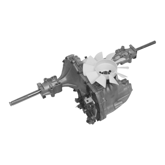
Page 6: External Features 310-0510
EXTERNAL FEATURES 310-0510 FRICTION PACK BELT KEEPER CONTROL ARM BRAKE ARM BRAKE DISC ADJUSTING PUCK BYPASS ARM Return to Neutral Option Friction Pack Option FILL PORT AXLE CLIP AXLE CLIP EXPANSION TANK INPUT SHAFT AXLE SHAFT AXLE CLIP AXLE CLIP... -
Page 7: Model Recognition
MODEL RECOGNITION 618-0319 166768 104-1760 173839 036932 618-0389A 310-0510 IHT... -
Page 8: Technical Specifications
20 inch; 508 mm 30 lb; 14 kg PRODUCT IDENTIFICATION The model and configuration of the 310-0510 IHT can be determined from the label shown in Figure 3. H Y D R O - G E A R H Y D R O - G E A R SULLIVAN, IL. -
Page 9: Section 2 Safety
PERSONAL SAFETY The floor should be clean and dry, and all ex- tension cords or similar trip hazards should be Certain safety precautions must be observed removed. while servicing or repairing the 310-0510 IHT. This section addresses some these... -
Page 10: Section 3 Troubleshooting
SECTION 3. TROUBLESHOOTING In many cases problems with the 310-0510 are WARNING not related to a defective transaxle, but are caused slipping drive belts, partially Do not attempt any servicing or adjust- engaged bypass valves, loose ments with engine running. -
Page 11: Section 4 Service And Maintenance
Figure 4 for the proper fill port location. input speed to the transmission. 4. Inspect the transmission cooling fan for Fill the 310-0510 to the top of the oil fill port. broken or distorted blades and remove any obstructions (grass clippings, leaves, dirt, Recheck the fluid level once the unit has been etc.). -
Page 12: Fluid Change
4. Position the transaxle so the oil will drain hydraulic components in the transaxle. completely out of the housing. As the 310-0510 transaxle is operated, oil in 5. After all the oil is drained from the transaxle, the transaxle housing heats up which causes remove the expansion tank by removing the the oil to expand. -
Page 13: Purging Procedures
3. High operation temperature and excessive expansion of oil. Before starting, make sure the transaxle/ transmission is at the proper oil level. If it is not, fill to the specifications outlined on page 10, Figure 4. 310-0510 IHT... -
Page 14: Return To Neutral Setting
3 and 4. Refer to Figure 5. 3. Start the engine and increase the throttle to full engine speed. Control Arm Brake Arm ROTATION B ROTATION A Bypass Arm Adjusting Puck Figure 5. Return to Neutral, Foot Control 310-0510 IHT... -
Page 15: Brake Maintenance
(11 Nm) torque. The friction pack nut is then backed off per the vehicle manufacturer’s specifications. BRAKE DISC FRICTION PACK NUT CONTROL ARM COTTER PIN BRAKE ARM BIAS SPRING BRAKE DISC Figure 7. Friction Pack TOP BRAKE PUCK CASTLE NUT Figure 6. Brake Components 310-0510 IHT... -
Page 16: Section 5 Repair
SECTION 5. REPAIR IMPORTANT: When internal repair is per- HOW TO USE THIS SECTION formed on the 310-0510 IHT, the filter assem- Each subassembly illustrated in this section is bly must be replaced. illustrated by an exploded view showing the TRANSAXLE REMOVAL parts involved. -
Page 17: Tools And Torques
TOOLS AND TORQUES Table 4. Required Tools Miscellaneous Sockets 310-0510 Service & Repair Manual 1/2"- 3/8" Adapter Flat Blade Screw Driver (2) 1/2" Deep Torque Wrench 7/16" Deep Air Impact Wrench 9/16" Deep Rubber Mallet 3/4" Deep Breaker Bar 7/8"... -
Page 18: Brake Assembly And Bypass Arm
5. Remove the brake rotor (59) and puck (60). and castle nut (69). Adjust the brake gap. Note: The hub on the rotor faces away from Refer to page 13. Install the brake arm bias the transaxle. spring (66). Figure 8. Brake Assembly and Bypass Arm 310-0510 IHT... -
Page 19: Control Arm And Friction Pack
13. 2. Inspect the control arm for wear or damage. 7. Install the brake assembly. See page 16. 76, 81, 88 Figure 9. Control Arm & Friction Pack 310-0510 IHT... -
Page 20: Seal Kit Replacement
9. Install the axle clips (93), if applicable. 2. The seal (51) can be replaced by following steps 3-6 of the procedure used to replace Input Seal the axle seals. 1. Remove the input pulley and fan from the Figure 10. Seal Kit Replacement 310-0510 IHT... -
Page 21: Side Housing
9. Install the control arm and friction pack. See 1. Inspect the bearing areas in the side hous- page 17. ing. 10. Install the bypass arm and brake assembly. See page 16. Bolt Torque Sequence Figure 11. Side Housing Assembly 310-0510 IHT... -
Page 22: Axle Shaft, Differential And Reduction Gears
10. Install the brake assembly and bypass arm. damage. See page 16. New Bull Gear/Differential Assembly (This is a direct replacement for the assembly illustrated to the right.) Figure 12. Axle Shaft, Differential & Reduction Gears (earlier bull gear shown) 310-0510 IHT... -
Page 23: Motor Shaft And Bypass Rod
1. Inspect the motor shaft (24), pinnion gear 8. Install the brake assembly and bypass arm. (27) and flat washers (52 & 108) for wear or See page 16. damage. Figure 13. Motor Shaft & Bypass Rod Assemblies 310-0510 IHT... -
Page 24: Input Shaft
INSPECTION 10. Install the control arm and friction pack. 1. Inspect the input shaft components for wear See page 17. or damage. 11. Install the brake assembly and bypass arm. See page 16. Figure 14. Input Shaft Assembly 310-0510 IHT... -
Page 25: Hydraulic Components
(3) for excessive wear or dam- semble the motor cylinder block. Check for age. NOTE: Piston seats may be held in piston/block wear in the cylinder bore. In- place in the piston by residual oil. spect the pistons, piston springs and piston 310-0510 IHT... - Page 26 2. Insert the thrust bearing (19) in the housing sure on the center section assembly (3, (1). NOTE: Place the thin race of the bear- Fig. 23). ing towards the housing bearing cavity. The thick race must face the pistons. 310-0510 IHT...
- Page 27 18. Figure 17 23. Fill the transaxle with new oil. See page 10. 24. Install the control arm and friction pack. See page 17. 25. Install the brake assembly and bypass arm. See page 16. Figure 18 310-0510 IHT...
- Page 28 HYDRAULIC COMPONENTS Axle Horn Figure 19 Figure 22 Figure 20 Figure 23 Short Shaft Post Figure 24. Swashplate/Pump Block Assembly Figure 21 310-0510 IHT...
-
Page 29: Transaxle Installation
See page 17. 9. Install the brake assembly and bypass arm. See page 16. 10. Install the transaxle onto the vehicle. 11. Perform the purge procedures listed on page 11. 12. Perform the return to neutral procedure on page 12. 310-0510 IHT... -
Page 30: Sealant Application
NOTE: Prior to applying the new sealant, the old sealant must be removed from all surfaces. A small consistent bead of the sealant around the housing face will be sufficient. Use sparingly. The illustration below indicates the correct areas. Sealant Path 310-0510 IHT... -
Page 31: 310-0610 & 310-0710 Iht
Note that larger (1") axle shafts make it necessary to specify a seal kit and axle bushings different from the 310-0510 unit. The center section, pump cylinder block assembly, and associated kits also differ from those on the 310-0510. Refer to the appropriate model schematic for specific component part numbers. -
Page 32: Parts List
310-0710 EXPLODED VIEW 310-0510 IHT... - Page 33 Washer, Thrust .59 x .79 x .04 20W-50 Oil Brake Yoke Kit Disk, Brake Brake Puck Puck Plate Brake Actuating Pin Bolt, Hex Head 1/4-20 x 2 w/patch Spacer Spring, Brake Arm Bias Arm, Brake Nut, Castle 5/16-24 Cotter Pin 3/32 X 3/4 310-0510 IHT...
- Page 34 310-0610 EXPLODED VIEW 310-0510 IHT...
- Page 35 Washer, Thrust .59 x .79 x .04 20W-50 Oil Brake Yoke Kit Yoke, Brake Bolt, Sq. Hd. 5/16-24 Ribbed Disk, Brake Brake Puck Puck Plate Brake Actuating Pin Bolt, Hex Head 1/4-20 x 2 w/patch Bolt, Hex Head 1/4-20 x 1 w/patch 310-0510 IHT...
- Page 36 310-0510 EXPLODED VIEW 310-0510 IHT...
- Page 37 310-0510 ITEMS LIST DESCRIPTION DESCRIPTION Main Housing, Assembly Nut, Castle 5/16-24 Main Housing, Machined Cotter Pin 3/32 x 3/4 Bushing .865 x .985 x .790 Compression Spring, Brake, Anti-Drag Pin, Standard Headless Washer, HT .51 x 1.0 x .03 Side Housing, Assembly Flat - Washer .34 x .88 x.06...
-
Page 38: Glossary Of Terms
Hydraulic Motor: A device which converts hydraulic fluid power into mechanical force and motion by transfer of flow under pressure. Hydraulic Pump: A device which converts mechanical force and motion into hydraulic fluid power by producing flow. Hydrostatic Pump: See “Hydraulic Pump” 310-0510 IHT... - Page 39 System Pressure: The pressure which overcomes the total resistance in a system, including all losses. Valve: A device which controls fluid flow direction, pressure, or flow rate. Variable Displacement Pump: A pump in which the displacement per cycle can be varied. Volumetric Displacement: The volume for one revolution. 310-0510 IHT...
- Page 40 © 2008 HYDRO-GEAR Printed in U.S.A. Rev. P2 310-0510 IHT...
Need help?
Do you have a question about the 310-0510 and is the answer not in the manual?
Questions and answers