Table of Contents
Advertisement
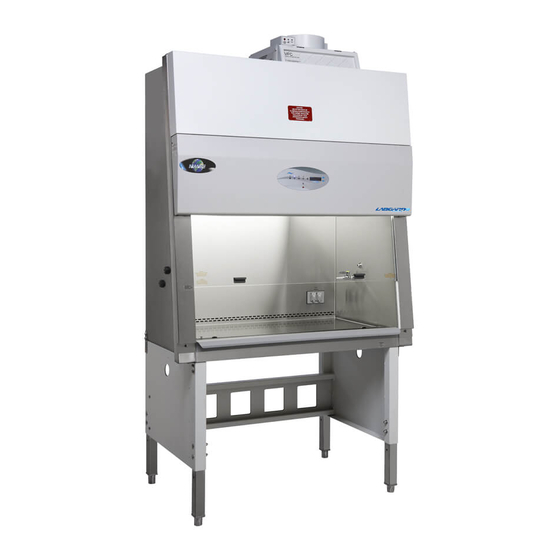
CELLGARD ES Energy Saver Class II,
Type A2 Laminar Flow
Biological Safety Cabinet
Models
NU-475-300/400/500/600
Bench/Console
Operation & Maintenance Manual
January, 2011
Revision 1
(Series 1 & Higher)
NU-475-400/500/600 Only
Manufactured by:
NuAire, Inc.
2100 Fernbrook Lane
Plymouth, Minnesota USA 55447
Toll Free: 1-800-328-3352
In MN: 763-553-1270
Fax: 763-553-0459
OM0196
Advertisement
Table of Contents

Subscribe to Our Youtube Channel
Summary of Contents for NuAire NU-475-300
- Page 1 CELLGARD ES Energy Saver Class II, Type A2 Laminar Flow Biological Safety Cabinet Models NU-475-300/400/500/600 Bench/Console Operation & Maintenance Manual January, 2011 Revision 1 (Series 1 & Higher) NU-475-400/500/600 Only Manufactured by: NuAire, Inc. 2100 Fernbrook Lane Plymouth, Minnesota USA 55447...
- Page 2 NSF/ANSI 49. Please read this manual carefully to familiarize you with proper installation, maintenance and operation of the cabinet. Other reference and guideline materials are available through the following web sites. www.hc-sc.gc.ca www.cdc.gov/od/ohs/ www.absa.org www.absa-canada.org www.ebsa.be www.inspection.gc.ca www.who.int www.biosafety.be www.hse.gov.uk www.nsf.org www.cetainternational.org www.osha.gov/dts/osta/ www.nuaire.com OM0196...
- Page 3 In case this manual and/or test report is lost or misplaced, NuAire retains a copy in our files. A replacement copy can be obtained by calling or writing NuAire, Inc. stating the model number and serial number and a brief description of the information desired.
-
Page 4: Table Of Contents
10.1 ................ Ultraviolet Light Section No. 11............Electrical/Environmental Requirements Section No. 12............Disposal and Recycle MANUAL DRAWINGS ACD-14251........NU-475 Airflow Schematic BCD-14243 ........NU-475-300 Specification Drawing BCD-14244 ........NU-475-400 Specification Drawing BCD-14245 ........NU-475-500 Specification Drawing BCD-14246 ........NU-475-600 Specification Drawing BCD-11815 ........Drain Valve Installation BCD-11816 ........Front Panel ASSEMBLY DRAWINGS BCD-05147 ........Base Stand Assembly... - Page 5 Center for Disease Control (CDC) Atlanta, Georgia. The NU-475 bench LFBSC is known as a Class II, Type A2 Biological Safety Cabinet. This is possible since NuAire's cabinet conforms to the following requirements: Maintains inflow velocity of 100 LFPM (.51m/s) through the work access opening.
- Page 6 Should you encounter problems that are not detailed adequately in the operating instructions, please contact your NuAire Representative of NuAire technical Services. Explanation of Symbols Safety alert symbol indicates a potentially hazardous situation which, if not avoided, could WARNING result in death of serious injury.
- Page 7 OM0196...
- Page 8 Models & Features The model NU-475, Class II, Type A2 Laminar Flow Biological Safety Cabinet is manufactured in four sizes: 3 ft., 4 ft., 5 ft., and 6 ft. OM0196...
- Page 9 OM0196...
- Page 10 OM0196...
- Page 11 OM0196...
- Page 12 OM0196...
- Page 13 Claims under this warranty should be directed to NuAire, Inc. setting forth in detail the nature of the defect, the date of the initial installation and the serial and model number of the equipment.
-
Page 14: Location
Per CDC/NIH and NSF it is strongly recommended that the cabinet be exhausted to the outside. NuAire offers a canopy type of exhaust transition, which will capture the exhaust efflux from the cabinet. - Page 15 5.2.4 Gas Service NuAire doesn't recommend the use of natural gas within the BSC, but if gas service is determined to be necessary for the application, appropriate safety measures must take place. All NuAire BSC's have precautionary warning labels that say the following:...
- Page 16 5.2.5 Plumbing Services Service ball valves with the type of service specified by the removable button on the handle are located in the work zone. The service ball valves are not recommended for pressure over 75 p.s.i. (5.2 BAR). Reducing valves should be installed external to the cabinet if necessary. Service ball valves should never be used for flammable gasses or oxygen service.
- Page 17 OM0196...
-
Page 18: Certification Testing Methods And Equipment
LFBSC. Certification Testing Methods and Equipment After installation and prior to use, NuAire recommends that the cabinet be certified or commissioned to factory standards. At a minimum, the following tests should be performed. HEPA filter leak test... - Page 19 CELLGARD ES Energy Saver Class II, Type A2 Laminar Flow Biological Safety Cabinet Models NU-475-300/400/500/600 Catalog Number Catalog Number NU-475-300 NU-475-400 NU-475-500 NU-475-600 Nominal 3 foot (0.9m) Nominal 4 foot (1.2m) Nominal 5 foot (1.5m) Nominal 6 foot (1.8m) Performance Specifications:...
-
Page 20: Operator Controls & Indicators
(pop-out button will appear) merely depress to reset. If the circuit breaker continually opens, a failure has occurred in the motor or solid-state speed controller. Consult a qualified repair technician or NuAire, Inc. for replacement. 6.1.2 Circuit Breaker-Outlets (Top of Control Center) The duplex outlet located in the sidewall of the work area is protected with a 3 amp circuit breaker. - Page 21 OM0196...
- Page 22 6.1.8 Airflow Calibration Potentiometer The operating airflows within the cabinet (i.e. 60 LFPM (.30 m/s) downflow and 105 LFPM (.53 m/s) air inflow barrier) are controlled by the DC motor speed control and an exhaust damper. The DC motor speed control controls the ECM motor by providing a Pulsed Width Modulation (PWM) signal of 2.5 to 8.0 Vdc that is sent to the ECM motor.
-
Page 23: Operating Guidelines
Operating Guidelines The intent herein is to present general operational guidelines that will aid in the use of the Laminar Flow Biological Safety Cabinet (LFBSC) to control airborne contaminants of low to moderate risk as stated in Technical Report No. FPS 56500000001 prepared by Dow Chemical U.S.A. for the National Cancer Institute, May 1, 1972. - Page 24 6.2.4 Utilize Unidirectional Air Flow The operator must keep two important facts in mind: (1) The air, as supplied to the work area through filters from the top, is contaminant free and (2) Airborne contamination generated in the work area is controlled by the unidirectional flow of parallel air streams in a top-to-bottom direction.
-
Page 25: Operating Sequence
Operating Sequence 6.3.1 Start Up Turn on cabinet blower and lights, check air intake and exhaust portals of the cabinet to make sure they are unobstructed. Note: Some cabinets are equipped with ultraviolet (UV) lights. Good procedure includes the decontamination or wipedown of cabinet surfaces with chemical disinfectant before work commences. -
Page 26: Ergonomics
6.3.6 Terminal Purging & Wipedown Following completion of work, allow the cabinet to run for 2-3 minute period without personnel activity to purge the unit. The decontamination of the interior surfaces should be repeated after removal of all materials, cultures, apparatus, etc. A careful check of grills and diffuser grids should be made for spilled or splashed nutrients which may support fungus growth and resulting spore liberation that contaminates the protected work environment. -
Page 27: Hazardous Drug Decontamination Procedure
CATUION: DISINFECTANTS THAT USE CHLORIDES AND HALOGENS WILL CAUSE DAMAGE TO THE STAINLESS STEEL SURFACES IF LEFT ON FOR LONG PERIODS OF TIME. After the specified contact time, wipe up excess disinfectant. IF THE DISINFECTANT USED CONTAINS CHLORIDES OR HALOGENS, RE-WIPE ALL SURFACES WITH 70% ALCOHOL OR SIMILAR NON-CORROSIVE ANTI-MICROBIAL AGENT TO PREVENT DAMAGE TO STAINLESS STEEL SURFACES. - Page 28 6.6.3 Assembly Replace front (if removed) grill. Replace the work tray and carefully tighten the thumbscrews. Replace perforated metal diffuser screen over the underside of the supply HEPA filter. Wipe down all exposed surfaces of the work area with 70% isopropyl alcohol. Prepare for aseptic operation.
-
Page 29: Decontamination
General Maintenance All maintenance actions on this equipment must be performed by a qualified CAUTION technician who is familiar with the proper maintenance procedures required for this equipment. This includes both certification as well as repair. Decontamination No maintenance should be performed on the interior of the CELLGARD ES cabinet (area behind access panels) unless the cabinet has been microbiologically decontaminated, is known to biologically clean, or known to be chemically inert. -
Page 30: Fluorescent Lamp Bulb Replacement
(See section 6.6 for guidelines) Please consult with NuAire, Inc. about any unique contamination problems. Normally, no preventive maintenance is required on the interior of the cabinet (i.e., the area behind the access panel containing the HEPA filters and motor (blower assembly). -
Page 31: Hepa Filter/Motor Replacement
HEPA Filter/Motor Replacement (Drawing BCD-11819) The HEPA Filters under normal usage and barring an accident (a puncture), do not need replacement until the efflux velocity cannot be maintained or the access inflow velocity cannot be maintained at 100 LFPM (.51 m/s ) (min.). This may permit the average downflow velocity to be as low as 55 LFPM (.28 m/s) as long as no point falls below 20% or +/-16fpm of the average downflow velocity, which ever is greater. - Page 32 Pull the exhaust choke tray free and remove the filter. It is not necessary to remove the tray, although it is free to move forward several inches, if necessary, to free the HEPA filter. Step 4: Filter Installation When installing new filters, USE ONLY NUAIRE SPECFIED FILTERS FOR REPLACEMENT. Description: Supply HEPA Filter Exhaust HEPA Filter Efficiency: 99.99% @ 0.3 Micron...
-
Page 33: Sliding Window Replacement & Adjustment
Since it has been NuAire's experience that the filters may not "load" evenly, choke adjustments may be necessary for proper cabinet performance. - Page 34 7.5.1 Downflow Calibration Place a velometer in the cabinet workzone on the horizontal plane 4 inches Step 1: (102mm) above the bottom edge of the viewing window. Spot check several points on the recommended downflow velocity test grid found in table 7.0. ...
- Page 35 7.5.2 Inflow Calibration Measure the inflow velocity using the recommended Step 1: procedure found in Table 7.0. If necessary, adjust the exhaust filter choke, located under the front decorative panel, to achieve the correct average inflow velocity within the stated range of 105 5 LFPM (.53 .025 m/s). ...
-
Page 36: Hepa Filter Leak Test
HEPA Filter Leak Test In order to check filter and filter seal integrity, the HEPA filter media and seals must be directly accessible, by the measuring instrument. The challenge material (i.e. PAO) should be supplied in the rear center of the workzone over the intake slots. -
Page 37: Site Installation Assessment Tests
Site Installation Assessment Tests These tests are performed to verify the sash position, airflow or pressure setpoint where an audible and/or visual alarm will activate to signify unfavorable operating conditions within the biological safety cabinet and/or the remote exhaust blower, and canopy connection performance. 7.8.1 Sash Alarm Step 1: With sash alarm switch enabled, raise the sliding sash 1”... -
Page 38: Cleanliness Classification Test For Pharmacy Application
Cleanliness Classification Test for Pharmacy Application If this cabinet is going to be used within pharmacy, per USP797 , the cabinet must be tested to assure compliance to ISO 14644-1:1999, Cleanrooms and Associated Controlled Environments, Part 1: Classification of Air Cleanliness . - Page 39 Table 7.0 Recommended Measurement Methods for Cabinet Downflow & Inflow Downflow Measurement Recommended Instruments: TSI 8355 Thermoanemometer Procedure: Supply filter efflux is measured on a grid, in a horizontal plane 4 inches (102mm) above the bottom edge of the window. No reading should be taken closer than 6 inches (152mm) from the inside perimeter.
- Page 40 Alternate Procedure: The alternative procedure to determine inflow velocity uses a thermoanemometer in a constricted window access opening of 3 inches (76mm) with the armrest removed. Inflow air velocity is measured in the center of the constricted opening 1-1/2 inches (38mm) blow the top of the work access opening on the following specified grid. Use the correction factor table to calculate the inflow velocity.
- Page 41 Error Indicators & Troubleshooting Audible alarms and error indicators occur for a variety of reasons. Whenever an alarm condition is present, the audible alarm and error indicator will be presented and stay on until the error is cleared. When presented with an error indicator, please perform the following: Step 1: NOTE ALL ERROR INDICATORS.
- Page 42 Error Indicator Indicator Correction Cabinet outlets won't turn on. Check outlet circuit breaker on top of control center. Check voltage to outlets. Cabinet ultraviolet light won't turn Check blower/light circuit breaker on top of control center. Check ultraviolet lamp. Check voltage to ultraviolet ballasts.
-
Page 43: Ultraviolet Light
10.0 Optional Equipment 10.1 Ultraviolet Light Ultraviolet light will injure your eyes. Avoid direct viewing at all times. CAUTION Personnel should not be present when ultraviolet lamp is on 10.1.1 Overview The germicidal ultraviolet is primarily intended for the destruction of bacteria and other microorganisms in the air or on directly exposed surfaces. - Page 44 Energies Required to Destroy Some Microorganisms By Ultraviolet Radiations(e) Microwatt Microwatt Mold Spores seconds Protozoa seconds per cm/2 per cm/2 Penicillum roqueforti 26,400 Paramecium 200,000(a) Penicillium expansum 22,000 Penicillium digitiatum 88,000 Nematode Eggs 40,000(b) Aspergillus glaucus 88,000 Aspergillus flavus 99,000 Algae 22,000(c) Aspergillus niger 330,000...
- Page 45 11.0 Electrical/Environmental Requirements 11.1 Electrical (Supply voltage fluctuations not to exceed +/- 10%) *NU-475-300 115V, 60Hz, 1 Phase, 12 Amps *NU-475-400 115V, 60Hz, 1 Phase, 12 Amps *NU-475-500 115V, 60Hz, 1 Phase, 14 Amps *NU-475-600 115V, 60Hz, 1 Phase, 14 Amps *UL/UL-C Listed 11.2...
- Page 46 12.0 Disposal and Recycle Cabinets that are no longer in use and are ready for disposal contain reusable materials. ALL components with the exception of the HEPA filters may be disposed and/or recycled after they are known to be properly disinfected.
- Page 47 OM0196...
- Page 48 OM0196...
- Page 49 OM0196...
- Page 50 OM0196...
- Page 51 OM0196...
- Page 52 OM0196...
- Page 53 OM0196...
Need help?
Do you have a question about the NU-475-300 and is the answer not in the manual?
Questions and answers