Table of Contents
Advertisement
Quick Links
Contents
Safety ............................................................................................................ 2
Section 1-Introduction ................................................................................. 3
General ......................................................................................................... 3
Product Description....................................................................................... 3
Differential Pressure Unit ......................................................................... 3
Electronic Transmitter................................................................................ 4
Power Supply ............................................................................................ 4
Zero and Span Control.................................................................................. 4
Zero Control .............................................................................................. 4
Span Control ............................................................................................. 5
Specifications ............................................................................................... 5
Qualification............................................................................................... 7
Section 2-Theory of Operation .................................................................... 9
Basic Components ........................................................................................ 9
Differential Pressure Unit (DPU) ............................................................... 9
Electronic Transmitter...............................................................................11
Basic Operation ...........................................................................................11
Surge Voltage Protection Circuit .............................................................11
Reverse Polarity Protection ......................................................................11
Regulator ..................................................................................................11
Strain Gage Bridge Network ................................................................... 12
Signal Amplifier........................................................................................ 12
Current Amplifier...................................................................................... 12
Temperature Compensation........................................................................ 12
Section 3-Installation, Startup, and Shutdown ........................................ 13
Overview ..................................................................................................... 13
Unpacking/Inspection.................................................................................. 13
Initial Calibration Check .............................................................................. 13
Mounting ..................................................................................................... 13
Wall or Rack Mounting ............................................................................ 13
Piping Guidelines ........................................................................................ 14
Electrical Connections ............................................................................... 14
Loop Resistance Calculations ................................................................. 16
Maximum Loop Resistance ..................................................................... 17
EMI/RFI Shielding ....................................................................................... 17
BARTON
MODEL 752 & 752A
®
DIFFERENTIAL PRESSURE
For Nuclear Service
TRANSMITTERS
User Manual
Part No. 9A-C10820, Rev. 02
November 2015
Advertisement
Table of Contents

Related Manuals for Cameron Barton 752

Summary of Contents for Cameron Barton 752
-
Page 1: Table Of Contents
BARTON MODEL 752 & 752A ® DIFFERENTIAL PRESSURE TRANSMITTERS For Nuclear Service User Manual Part No. 9A-C10820, Rev. 02 November 2015 Contents Safety ......................2 Section 1—Introduction ................. 3 General ......................3 Product Description..................3 Differential Pressure Unit ................. 3 Electronic Transmitter................ -
Page 2: Safety
Startup Procedure ..................17 Shutdown Procedure .................. 18 Section 4—Calibration and Maintenance ........... 19 General Field and Periodic Maintenance ............ 19 Electronic Transmitter................19 Differential Pressure Unit (DPU) ............. 19 Calibration ....................19 Electrical Connections for Calibration ............. 20 Calibration Checkpoints ................21 Calibration Procedure ................ -
Page 3: Section 1-Introduction
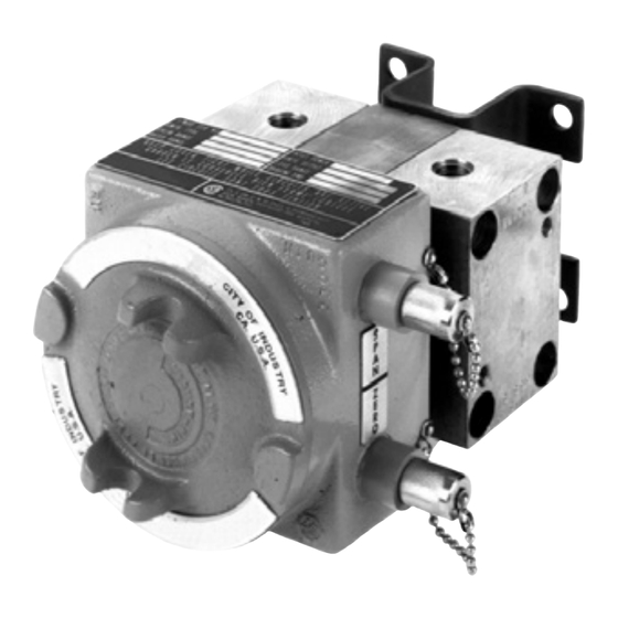
Model 752 and 752A Differential Pressure Transmitters Section 1 Section 1—Introduction General The Model 752 and 752A Differential Pressure Transmitters provide a 4-20 mA or 10-50 mA signal that is proportional to differential pressure and trans- mits it to remote receiving, control, or readout devices. Sources of differential pressure include liquid level and specific gravity changes in vessels;... -
Page 4: Electronic Transmitter
Section 1 Model 752 and 752A Differential Pressure Transmitters Electronic Transmitter The electronic transmitter supplies a 4-20 mA or 10-50 mA direct current out- put signal that is proportional to the differential pressure sensed by the DPU. The output signal is transmitted over a two-wire transmission line to remote receiving devices. -
Page 5: Span Control
Model 752 and 752A Differential Pressure Transmitters Section 1 Span Control When a transmitter leaves the factory, it has a fixed range—0-120”w.c., 0-63 psi, etc. Typically the output from the transmitter varies from 4-20 mA or 10- 50 mA. This output is linear with the measured variable, as shown in Figure 1.2. - Page 6 Section 1 Model 752 and 752A Differential Pressure Transmitters Specifications (cont'd) Load Range (includes line and receiver; see Figure 3.3, page 4-20 mA ........50 ohms per volt above 12 VDC (to 2900 ohms maximum) 10-50 mA ........20 ohms per volt above 12 VDC (to 1160 ohms maximum) Load Effect* 4-20 mA ........
-
Page 7: Qualification
Model 752 and 752A Differential Pressure Transmitters Section 1 Qualification The Model 752 and 752A transmitters have been subjected to IEEE-344 qualification testing that demonstrates that the unit will not lose its pressure boundary or structural integrity when subjected to loadings associated with seismic accelerations up to 12 Gs. - Page 8 Section 1 Model 752 and 752A Differential Pressure Transmitters...
-
Page 9: Section 2-Theory Of Operation
Model 752 and 752A Differential Pressure Transmitters Section 2 Section 2—Theory of Operation Basic Components Differential Pressure Unit (DPU) Valve Stem HP Housing LP Housing HP Bellows LP Bellows Figure 2.1—DPU cutaway view The differential pressure range of the dual-bellows type DPU is determined by the force required to move the bellows through their normal range of travel. - Page 10 Section 2 Model 752 and 752A Differential Pressure Transmitters Temperature Compensation. The high pressure side of the DPU has extra bellows convolutions to provide for expansion and contraction of the fill liquid caused by ambient temperature changes. These extra convolutions are connected to the measuring bellows by a passageway to permit the fill liquid to change volume without materially affecting the internal pressure or the physical relationship of the measuring bellows.
-
Page 11: Electronic Transmitter
Model 752 and 752A Differential Pressure Transmitters Section 2 Electronic Transmitter The DPU senses the difference in pressure applied across the bellows unit assembly and the electronic circuit converts to a 4-20 mA or 10-50 mA output signal. The pressure causes a linear motion of the bellows which is mechani- cally transmitted to the strain gages by the strain gage beam. -
Page 12: Strain Gage Bridge Network
Section 2 Model 752 and 752A Differential Pressure Transmitters Figure 2.3—Operational block diagram Strain Gage Bridge Network The strain gage bridge network consists of two silicone piezo-resistive strain sensors, the zero adjusting potentiometer, bridge completion resistors, and the temperature compensation components. Signal Amplifier The signal amplifier is an integrated circuit operational amplifier which pro- vides amplification of the strain gage bridge network output voltage. -
Page 13: Section 3-Installation, Startup, And Shutdown
Model 752 and 752A Differential Pressure Transmitter Section 3 Section 3—Installation, Startup, and Shutdown Overview This section describes the steps required to install the instrument so that it will perform to its original factory calibration condition. Installation tasks include • initial calibration check •... -
Page 14: Piping Guidelines
Section 3 Model 752 and 752A Differential Pressure Transmitters Piping Guidelines Observe the following practices when piping for flow and liquid level ap- plications. Install the transmitter as near the primary metering device as possible, and choose a piping diameter accordingly. For distances up to 50 feet, use 1/4-inch pipe or tubing. - Page 15 Model 752 and 752A Differential Pressure Transmitter Section 3 Perform the following steps to complete field wiring. Connect the power supply and the receiver to the transmitter as shown in Figures 3.1 and 3.2. Determine the total loop resistance required for the installation, using Figure 3.3, page 16, for reference.
-
Page 16: Loop Resistance Calculations
Section 3 Model 752 and 752A Differential Pressure Transmitters Table 3.1—Cable Specifications Loop Resistance/1000 ft Cable Wire Size (ohms @ 20°C) 5.06 14 AWG, 2 Wires 8.04 16 AWG, 2 Wires 12.78 18 AWG, 2 Wires 20.30 20 AWG, 2 Wires 2900 1160 Any voltage or resistance within the shaded area for the respective transmitter output is acceptable. -
Page 17: Maximum Loop Resistance
Model 752 and 752A Differential Pressure Transmitter Section 3 Maximum Loop Resistance Example 1: (Maximum loop resistance for 10-50 mA system): = 70 Vdc = 12 Vdc 70-12 = 50 mA = 1160 Ohms 0.05 Example 2: (Maximum loop resistance for 4-20 mA system): = 70 Vdc = 12 Vdc 70-12... -
Page 18: Shutdown Procedure
Section 3 Model 752 and 752A Differential Pressure Transmitters monitored). Follow the guidelines in Appendix A that are specific to your piping configuration. 3. Open the block valves if applicable (recommended for liquid service, but not for gas). NOTE: For gas service, it is recommended that a zero check be performed with both block valves closed. -
Page 19: Section 4-Calibration And Maintenance
Model 752 and 752A Differential Pressure Transmitters Section 4 Section 4—Calibration and Maintenance General Field and Periodic Maintenance Electronic Transmitter The electronic transmitter circuits are basically maintenance-free and do not require routine preventative maintenance other than a periodic check of cali- bration. -
Page 20: Electrical Connections For Calibration
Section 4 Model 752 and 752A Differential Pressure Transmitters Table 4.1—Calibration Equipment Equipment Requirements Digital Voltmeter ±0.05% of reading accuracy at 10 VDC scale Power Supply 12-70 Vdc, 60 mA minimum, regulation 3%, ripple 1% (see Electrical Connections, page Precision Load Resistor 200 ohms, ±0.05%, 1W (10-50 mA transmitter) 500 ohms, ±0.05%, 1W (4-20 mA transmitter) Pressure Source... -
Page 21: Calibration Checkpoints
Model 752 and 752A Differential Pressure Transmitters Section 4 Install a load resistor sized for the application. WARNING: Failure to properly calculate power supply DC output voltage may result in inaccurate transmitter readings, possibly leading to safety system performance degradation during design basis events. To avoid equipment inaccuracy hazards, follow the examples and tables in this section for determining the proper power supply DC output voltage. -
Page 22: Dpu Inspection And Cleaning
Section 4 Model 752 and 752A Differential Pressure Transmitters cess being monitored from the monitoring instruments. Configure the test manifold control valve to connect the output of the test pressure source to the high port of the DPU and vent the low side of the DPU to atmosphere. -
Page 23: Troubleshooting
Model 752 and 752A Differential Pressure Transmitters Section 4 Replace the housings (new O-rings are recommended) and 3/8" CRES head bolts. Apply Molycoat G paste or similar lubricant to threads and under heads (bearing surface) of bolts. Do not use silicone oil or grease. Torque the head bolts to 45 ft-lb to a rotation of up to 135 degrees nomi- nal using a torque wrench. - Page 24 Section 4 Model 752 and 752A Differential Pressure Transmitters Table 4.3—DPU Troubleshooting Problem Possible Probable Cause Corrective Action Source High Primary Orifice partially restricted or too Clean out or Output Element small; replace; Loss of liquid in reference leg Refill reference leg (liquid level) Piping from Leak in LP side piping...
- Page 25 Model 752 and 752A Differential Pressure Transmitters Section 4 Table 4.4—Transmitter Troubleshooting Problem Possible Probable Cause Corrective Action Source No Output Power Blown fuse, faulty Replace fuse, repair Source component power supply Transmission Loose terminal connection Tighten terminal Cable connection; locate and replace broken wire Receiver...
- Page 26 Section 4 Model 752 and 752A Differential Pressure Transmitters...
-
Page 27: Section 5-Assembly Drawing And Parts List
Model 752 and 752A Differential Pressure Transmitters Section 5 Section 5—Assembly Drawing and Parts List Figure 5.1—Model 752 and 752A, front view... - Page 28 Section 5 Model 752 and 752A Differential Pressure Transmitters W ARNING: Items marked with an asterisk (*) below may be replaced with- out loss of instrument qualification. No other field repairs or component replacements are authorized if instrument qualification is to be main- tained. Table 5.1—752 and 752A Parts List ITEM DESCRIPTION PART NO. UNIT Enclosure cover (gray) 9A-C0039-1045C Model 752 circuit board assembly, 4 to 20 mA 9A-C0752-1056B (replacements no longer available) Model 752 circuit board assembly, 10 to 50 mA 9A-C0752-1070B (replacements no longer available)
- Page 29 Model 752 and 752A Differential Pressure Transmitters Section 5 Table 5.1—752 and 752A Parts List ITEM DESCRIPTION PART NO. UNIT 9A-C0752-1004C Junction box 9A-C0752-1114C Data plate 9C-C0752-1172G I.D. plate, span adjust 9A-C0752-1121C I.D. plate, zero adjust 9A-C0752-1122C Silicone grease 9A-C0002-1003U Drive screw, 00 9A-C0600-1001J Drive screw, #2...
- Page 30 Section 5 Model 752 and 752A Differential Pressure Transmitters...
-
Page 31: Section 6-Dimensional Drawings
Model 752 and 752A Differential Pressure Transmitters Section 6 Section 6—Dimensional Drawings Figure 6.1—Model 752 and 752A transmitters with junction box, front view Figure 6.2—Model 752 and 752A transmitters with junction box, side view... - Page 32 Section 6 Model 752 and 752A Differential Pressure Transmitters Figure 6.3—Model 752 and 752A transmitters, rear view...
-
Page 33: Safety Precautions
Model 752 and 752A Differential Pressure Transmitters Appendix A Appendix A Safety Precautions Suggested piping diagrams and startup instructions for typical and special flow applications are presented on the following pages. WARNING HIGH-PRESSURE HAZARD. TO PREVENT PERSONAL INJURY OR DAMAGE TO EQUIPMENT, DIRECT ALL PIPING AWAY FROM THE OPERATOR WHILE CONNECTING THE DPU TO THE SYSTEM PIPING. -
Page 34: Typical Piping/Startup Examples
Appendix A Model 752 and 752A Differential Pressure Transmitters Typical Piping/Startup Examples Diagrams for typical and special flow applications are presented on the fol- lowing pages. Use the diagram best suited for the application as a guide for piping configuration. Gas Flow, DPU Above Run The following steps are recommended for applications in which hydrates are NOT present. -
Page 35: Gas Flow, Dpu Below Run
Model 752 and 752A Differential Pressure Transmitters Appendix A Gas Flow, DPU Below Run The following steps are recommended only for applications that require the DPU to be mounted below the run. Drip pots are required when wet gas is present. -
Page 36: Gas Flow, Hydrates Present
Appendix A Model 752 and 752A Differential Pressure Transmitters Gas Flow, Hydrates Present The following steps are recommended for applications in which hydrates or heavy solids are present, and piping and shutoff valves are not less than 1/2-inch in diameter. Bypass the manifold above to isolate the meter from connecting piping. -
Page 37: Steam Flow, Dpu Below Run
Model 752 and 752A Differential Pressure Transmitters Appendix A Steam Flow, DPU Below Run For this application, condensing reservoirs and piping to orifice taps must be level. Assure that the reservoir and steam lines are at the same level. Two-inch pipe crosses may be used as seal pots. -
Page 38: Liquid Flow, Dpu Above Run
Appendix A Model 752 and 752A Differential Pressure Transmitters Liquid Flow, DPU Above Run The following steps are recommended for applications in which sediments may be present. Inspect piping periodically. Not recommended for hot or gassy liquids. Close both shutoff valves and open both block valves. Open the bypass valve. -
Page 39: Liquid Flow, Dpu Below Run
Model 752 and 752A Differential Pressure Transmitters Appendix A Liquid Flow, DPU Below Run The following steps are recommended for hot or gassy liquids. Periodic in- spections of piping are recommended. Close both shutoff valves and open both block valves. Open the bypass valve. -
Page 40: Dpu Below Tank With Reference Leg: Hot Or Cool Liquids
Appendix A Model 752 and 752A Differential Pressure Transmitters DPU Below Tank with Reference Leg: Hot or Cool Liquids The use of a reference leg cancels out the "dead leg" (piping from the tank bottom to center line of meter body). Seal fluid in the reference leg must not volatilize. -
Page 41: Dpu Level With Tank Bottom: Cool Liquids With Pressurized Tank
Model 752 and 752A Differential Pressure Transmitters Appendix A DPU Level with Tank Bottom: Cool Liquids with Pressurized Tank Open the block valves and shutoff valves. Crack open the DPU low-pressure drain valve and close it when liquid stops flowing from it. Crack open the DPU high-pressure vent valve and close it when bubble- free liquid flows from it. -
Page 42: Dpu Below Tank Bottom: Cool Liquids With Pressurized Tank
Appendix A Model 752 and 752A Differential Pressure Transmitters DPU Below Tank Bottom: Cool Liquids with Pressurized Tank Open the block valves and shutoff valves. Crack open the DPU low-pressure drain valve and close it when liquid stops flowing from it. Crack open the DPU high-pressure drain valve and close it when bubble- free liquid flows from it. -
Page 43: Product Warranty
If any defect within this warranty appears, Buyer shall notify Cameron immediately Cameron agrees to repair or furnish a replacement for, but not install, any product which within one (1) year from the date of shipment by Cameron shall, upon test and examination by Cameron, prove defective within the above warranty. - Page 44 HEADQUARTERS (HOUSTON, TX) UNITED STATES CANADA 1.281.582.9500 1.800.654-3760 1.403.291.4814 ms-us@c-a-m.com ms-canada@c-a-m.com INDIA LATIN AMERICA ASIA PACIFIC 91.982.2431686 +55.21.2172.9714 +603.7954.0145 ms-ind@c-a-m.com ms-latinamerica@c-a-m.com ms-kl@c-a-m.com MIDDLE EAST & NORTH AFRICA EUROPE, CASPIAN, RUSSIA & S. AFRICA 971.4802.7700 +44.1892.518000 ms-me@c-a-m.com ms-uk@c-a-m.com w w w . c - a - m . c o m / m e a s u r e m e n t...
Need help?
Do you have a question about the Barton 752 and is the answer not in the manual?
Questions and answers