
Summary of Contents for Imperial Systems CMAXX
- Page 1 DUST & FUME COLLECTION SYSTEM Installation, Operation, & Maintenance Manual 73 2 0 We s t M a r ke t S t . M e rc e r, PA 1 6 1 37 8 0 0. 9 1 8 . 3 0 1 3 i m p e r i a l s ys t e m s i n c .c o m...
-
Page 2: Table Of Contents
C O N T E N T S Introduction and Warranty Introduction Serial Number Warranty IDA In-Line Deflagration Arrester Certification Fire Protection And Safety Equipment Safety Safety Alert Symbol And Signal Words Operational Hazards 2.2.1 Prepare For Emergencies 2.2.2 Replace Safety Signs Maintenance Hazards Hazards From Modifying Equipment Pressurized Air Hazards... - Page 3 6.1.9 Down Time Cycles (min) 6.1.10 Auto Alarm Reset (sec) (Only With DCP Installed) Maintenance Support and Diagnostics Startup Maintenance Filter Handling And Replacement Safety Valve Maintenance CMAXX Spare Parts Troubleshooting 10. Quick Reference Guide Electrical 11.1 Solenoid Schematic 11.2 DCT1000 Schematic 11.3...
-
Page 4: Introduction And Warranty
The serial number plate is located in the lower left Congratulations on your purchase of an Imperial corner of the door below the CMAXX sticker. Systems, Inc. product. This product has been designed For future reference, write your serial number in the and manufactured to the strictest specifications. -
Page 5: Warranty
Imperial Systems, Inc. liability. workmanship for Fifteen (15) years from the date of Imperial Systems, Inc. shall not be liable for any other shipment, if properly installed, maintained and costs, expenses or damages, whether direct, indirect, operated under normal conditions. -
Page 6: Ida In-Line Deflagration Arrester Certification
The IDA certification is optional. Contact Imperial there is no deformation or stress cracks in latch mechanism. 4. Inspect lift rails for proper function. Systems to verify if your CMAXX is equipped with the IDA certification. 5. Replace filters with Certified DELTAMAXX IDA The CMAXX using the Proprietary DELTAMAXX IDA Filters. -
Page 7: Safety
Additional information may be found at: www.nfpa.org or www.osha.gov. NOTICE If you do not understand any part of this manual, contact Imperial Systems, Inc. at 724-662-2801. NOTICE - Indicates a situation that could result in damage to the equipment or other property. -
Page 8: Prepare For Emergencies
Safety sign locations are identified in Section 3 of this manual. the manufacturers’ warranty. Replacement safety signs are available from Imperial Systems, Inc. 2.5 Pressurized Air Hazards 2.3 Maintenance Hazards Compressed air can cause serious injury or death. -
Page 9: Safety Labels
3. Safety Labels impe rialsyste msin c.co m I mp e ri a l System s I nc . -
Page 10: Unloading Equipment
4.1 RECOMMENDED TOOLS AND EQUIPMENT 5.1 ASSEMBLY 1. Locate and assemble the support structurer according to the • Screw Pin Clevis assembly drawing that came with your CMAXX. Leave all of the • Crane or Forklift hardware loose at this time. • Drift Pins •... -
Page 11: Compressed Air Installation
Supply line must be minimum 1 in. diameter. Use pipe sealant or thread sealing tape on 5. Properly rig the body of the CMAXX and lift into place over the all compressed air connections. -
Page 12: Electrical
CMAXX DIAPHRAGM VALVE AIR CONSUMPTION @ 80 PSI 1'' Diaphragm Valve 1.5” Diaphragm Valve On Time (msec) 31.2 62.4 96.0 33.6 66.0 102.0 15.6 31.2 48.0 16.8 33.0 51.0 10.4 20.8 32.0 11.2 22.0 34.0 15.6 24.0 16.5 25.5 12.5 19.2... -
Page 13: Differential Pressure Kit Installation
3. The differential pressure kit comes with a 100’ roll of silver tubing. Note: Supply voltage to the timer controller must match the rated this tubing will be used to connect the high-pressure port on the CMAXX voltage of the pilot valve solenoids. -
Page 14: Dct1000 Controller Timer
important when multiple modules are installed. The last out-put value 6. DCT1000 CONTROLLER TIMER flashed will be the sum of all channels available in the system. The DCT1000 Dust Collector Timer Controller was designed to be used After the last available channel indication has completed, the currently with pulse-jet type dust collectors for on-demand or continuous programmed last channel value is displayed. -
Page 15: Low Limit (Only With Dcp Installed)
6.1.5 Low Limit (Only With DCP Installed) 6.1.10 Auto Alarm Reset (sec) (Only With DCP Installed) The operation of the Low Limit, available only with a pressure The Auto Alarm Reset Setup, available only when a pressure module module installed, is identical to the High Limit except this value sets is installed, allows the auto alarm reset time to be selected. -
Page 16: Startup
6. Set timer controller to on demand for normal operation. 7. Verify that pressure ports on body of CMAXX are plumbed to timer controller. 8. If using a drum kit with slide gate, make sure slide gate is open and drum is connected and sealed. -
Page 17: Maintenance
8. MAINTENANCE 3. Once both lift rails are lowered, filter can then be removed from unit by pulling filter out by top pan. Handling filter by paper filter 8.1 FILTER HANDLING AND REPLACEMENT media can permanently damage filter. NOTICE Improper handling of a filter can ruin the filter Filter Handling: Any rough handling of the paper media may result in a ruined filter. -
Page 18: Cmaxx Spare Parts
8.3 CMAXX SPARE PARTS CM AXX SPARE PARTS C M AXX CA RTRIDGE F I LTERS - DE LTAMAX X Na no f ib e r Pa r t # De script io n 4 6001 0.01 3 350 ft Nano ber Filter 350 ft Fire Retardant Nano ber Filter 4 6001 0.002... - Page 19 De script io n 43 0057 Rope Caulk 100' Roll 996 01 3.01 0 Imperial Grey CMAXX Touch Up Paint (Spray Can) Cont a ct Fa cto ry Imperial Blue Header Tank Touch Up Paint (Spray Can) Cartridge Removal Tool 3 Deep, 4-8ft...
-
Page 20: Troubleshooting
9. TROUBLESHOOTING PROBLEM PROBABLE CAUSE SOLUTION Blower fan motor does not start Improper motor wire size. Rewire using the correct wire gauges as specified by national and local codes. Motor not wired properly. See motor manufacturers wiring diagram. Check and correct motor wiring for the supply voltage present. - Page 21 PROBLEM PROBABLE CAUSE SOLUTION Insu cient airflow. Recalibrate DCP pressure module with Display on Delta P dosent return to zero when pressure tubing attached as described in timer at rest. controller installation. On Demand pressure cleaning does not start. Check tubing for kinks, breaks, contamination, High setpoint not adjusted for system or loose connections.
-
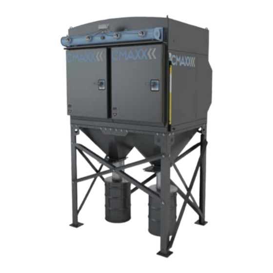
Page 22: Quick Reference Guide
10. QUICK REFERENCE GUIDE Silencer Solenoid Enclosure Pressure Relief Valve Pressure Gauge Diaphram Valve Compressed Air Fitting Differential Low Pressure Port Differential High Pressure Port Filter Removal Tool Door Handle Hopper Manual Slide Gate Flex Hose Collection Drum Kit Header Tank Serial Tag Dirty Air Inlet impe r ialsystemsin c.co m... - Page 23 Lifting Lug Clean Air Plenum Dirty Air Plenum Access Door Filter Pulse Pipe Filter Cleaning Nozzle Tube Sheet Filter Gasket Filter Pan Pleated Filter Material Filter Lift Rail Handle impe r ialsystemsin c.co m I m pe r ia l System s I nc .
-
Page 24: Electrical
11. ELECTRICAL 11.1 SOLENOID SCHEMATIC impe rialsyste msin c.co m I mp e ri a l System s I n c. -
Page 25: Dct1000 Schematic
11.2 DCT1000 SCHEMATIC i mper ialsyste msin c.co m I m p e ri al System s I nc . -
Page 26: Solenoid Heater Schematic (Optional)
11.3 SOLENOID HEATER SCHEMATIC (OPTIONAL) i mp er ialsystemsin c.co m I m p er i al System s I n c. -
Page 27: Integrated Controls Wiring Diagram
11.4 INTEGRATED CONTROLS WIRING DIAGRAM imper ialsystemsinc.com I m p e ri al System s I nc . - Page 28 MADE IN THE 8 0 0 . 9 1 8 . 3 0 1 3 i m p e r i a l s y s t e m s i n c . c o m...
Need help?
Do you have a question about the CMAXX and is the answer not in the manual?
Questions and answers