Table of Contents
Advertisement
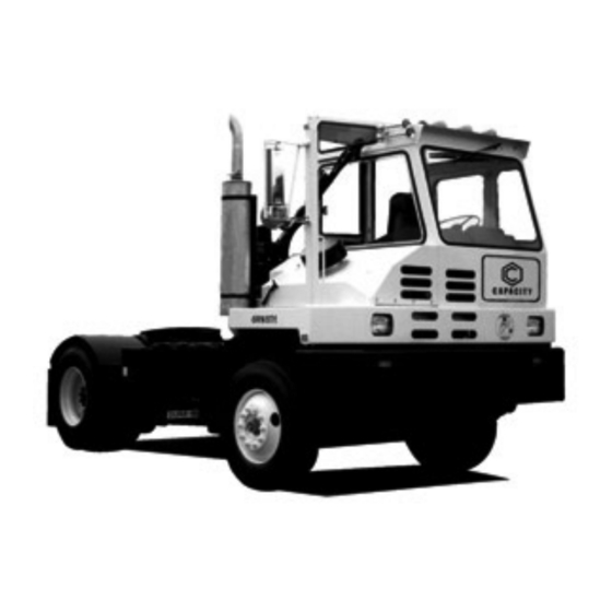
C A P A C I T Y
Operator's Handbook
Trailer Spotting Tractor
WARNING!
Failure to read, understand, and fully comply with the important information
contained in this Operator's Handbook may result in hazardous conditions or
cause a hazardous condition to develop.
Capacity of Texas, Inc.
401 Capacity Drive
Longview, TX 75604
1-800-323-0135
Advertisement
Table of Contents


Need help?
Do you have a question about the TJ5000 OFF ROAD and is the answer not in the manual?
Questions and answers
El capaciy no le entra el cambio de queda flachando el selector
The selector is flashing and not allowing gear changes because the shift to Drive (D) is not attained. This may be due to an active inhibitor or a service brake inhibit. Applying the service brakes is required when selecting Drive to prevent unexpected vehicle movement and to satisfy the brake inhibit condition.
This answer is automatically generated