
Summary of Contents for Hypex Electronics PSC2.400
- Page 1 Hypex Electronics BV Kattegat 8 9723 JP Groningen, The Netherlands +31 50 526 4993 sales@hypex.nl www.hypex.nl User Manual owered peaker ontroller PSC2.400...
-
Page 2: Table Of Contents
PSC2.400 User manual R5 Table of contents Product description ......................3 Type remarks........................3 Features ..........................3 Applications........................3 Connections........................4 System information ......................6 Description.......................... 6 Audio performance data ....................6 Hardware Architecture ...................... 7 Digital audio input......................7 Controllers .......................... -
Page 3: Product Description
1.4 or higher of the Hypex Filter Design program! In earlier versions the PSC is not yet implemented. The first time the PSC2.400 is used all biquads are zero, so there are no filters installed When you switch to Bridged mode please be sure to connect your speakers like described in this manual Do note that the Firmware update differs to the AS2.100 firmware update. -
Page 4: Connections
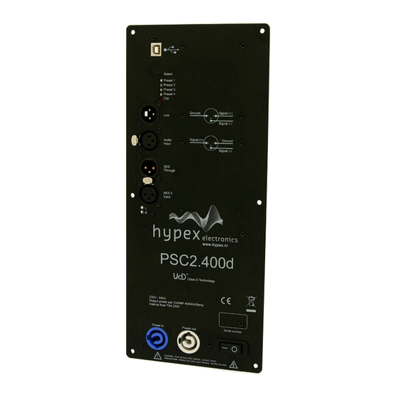
PSC2.400 User manual R5 Connections Figure 1 Overview of the connections on the front of the PSC2.400 Function USB input Select button Preset LED’s Clip detect LED Analogue Link Analogue Audio Input Power input Power output On/Off switch - 4 -... - Page 5 AES Though AES 3 Input AES input channel LED’s Figure Figure Figure Figure 2 2 2 2 Overview of the connections on the back of the PSC2.400 Function Function Function Function 1 1 1 1 J16, Speaker - 2 2 2 2...
-
Page 6: System Information
PSC2.400 User manual R5 System information Figure 4: Block diagram Two-channel active amplifier with DSP filter control. Description The PSC2 is a plate amp for use in powered speaker systems. As an active speaker controller, a PSC2 can form the basis of a powerful active two-way monitor. -
Page 7: Hardware Architecture
Controllers The PSC2.400 can only be controlled through USB. When the module is powered on it will automati- cally start up with the last settings. All setting, like volume and preset, are stored after a change is made. -
Page 8: Product Overview
Please do not connect any speakers to your system yet! Hardware part The PSC2.400 can be used in 2 ways, as a 2- channel setup or as a one channel bridged version for more power. This is selected in software. -
Page 9: Software Installation
PSC2.400 User manual R5 Software installation System requirements: Pentium class or higher • 64MB RAM • USB1.0 or higher • Tested on Windows XP and Vista All files are compressed in the setup.zip file. This zip file contains 1 DLL file for communication and an .EXE file, which represents the Hypex DSP filter design program. -
Page 10: Filter Design
PSC2.400 User manual R5 The last thing that can be controlled in this window is volume. This can be done by setting the scroll- bar to a desired position or by typing the value in the volume field, the value is send when pressed “enter”. -
Page 11: Graph Area
PSC2.400 User manual R5 Graph Area The magnitude tab shows the imported driver responses, filters, individual biquads, individual fil- tered driver responses and the sum. Colour Function Blue, thin Measured woofer response Green, thin Measured midrange response Red. thin Measured tweeter response... - Page 12 PSC2.400 User manual R5 Perform impulse response measurements for each driver separately. Save the entire impulse record – truncation can be done later on the filter design program. Measuring using an external amplifier A separate amplifier may also be used for measuring the drivers, provided the amplifier’s output impedance is as low as the DSP unit’s.
-
Page 13: Designing Filters
PSC2.400 User manual R5 this frequency. A way of obtaining quasi anechoic low-frequency measurements is making close-up measurements. Working with such measurements requires a good deal of interpretation but it is doable. Important: Avoid making any corrections for which no anechoic data is available. If reflections are... -
Page 14: Download
PSC2.400 User manual R5 The second step is designing the actual crossover filters. All the usual strategies work. Delaying higher frequency drivers with respect to lower-frequency ones is a powerful alternative to using asymmetric slopes and yields substantially improved coherence through the crossover region. -
Page 15: Safety Precautions
User manual R5 Safety precautions The PSC2.400 is supplied with a switched mode power supply. The following chapter explains the safety precautions which have to be made for these kinds of products. The SMPS400 operates at mains voltage and carries hazardous voltages at accessible parts. -
Page 16: Recommended Operating Conditions For The Smps
PSC2.400 User manual R5 This symbol indicates the presence of hazardous voltages at accessible conductive terminals on the board. Parts that are not highlighted in red (picture above) may carry voltages in ex- cess of 140VDC! 1. Read these instructions. -
Page 17: Mains Selection
User manual R5 Mains selection The PSC2.400 is factory set to operate at a mains voltage of 230Volt. The user is able to change this setting to 115Volt. Instructions must be followed! Before changing the mains settings disconnect the unit from the mains and allow all ca- pacitors to discharge for 10 minutes before handling it. -
Page 18: Technical Data
PSC2.400 User manual R5 Technical data Supply voltage 230Volt AC/50Hz +/- 10% (switch able to 115Volt 60Hz) Dimensions 142mmx330mmx55mm (WxHxD) Plate thickness 2,5mm Weight 1,1 kg Clearance >9,5mm Figure 16: Plate amp 2xUcD400Watt - 18 -... - Page 19 PSC2.400 User manual R5 Revision PCB Version Description Date PSC2 V0.1 - Initial Draft. 21-04-2009 PSC2 V0.2 - Hard- and software part added 06-10-2009 PSC2 V1 - Pinout description added 23-06-2010 - Clip limiter added PSC2 V1 - Safety instructions added...
Need help?
Do you have a question about the PSC2.400 and is the answer not in the manual?
Questions and answers