Table of Contents

Summary of Contents for Amarex KRT series
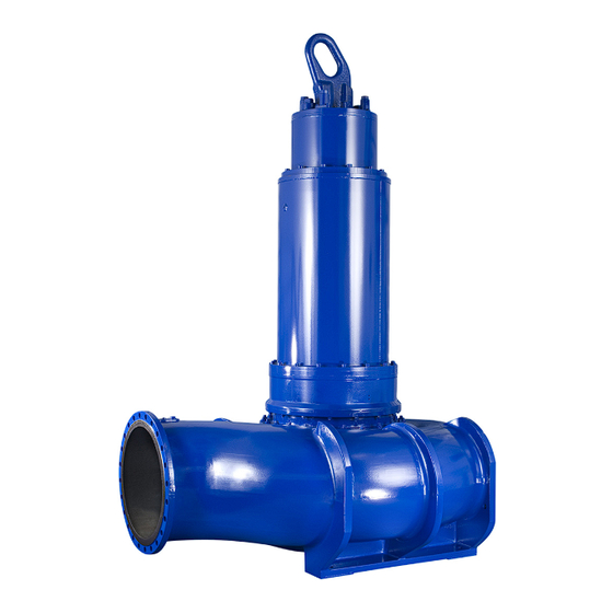
- Page 1 Submersible Motor Pump Amarex KRT Sizes DN 200 to DN 700; 60 Hz 6 poles: 530 6_N to 850 6_N 8 poles: 460 8_N to 760 8_N 10 poles: 390 10_N to 660 10_N 12 poles: 340 12_N to 560 12_N Installation/Operating Manual Mat.
- Page 2 Legal information/Copyright Installation/Operating Manual Amarex KRT Original operating manual All rights reserved. The contents provided herein must neither be distributed, copied, reproduced, edited or processed for any other purpose, nor otherwise transmitted, published or made available to a third party without the manufacturer's express written consent.
-
Page 3: Table Of Contents
5.2.6 Checking the direction of rotation .................... 24 Installing the pump set .......................... 25 5.3.1 Stationary wet installation ........................ 26 5.3.2 Stationary dry installation ......................... 34 Electrical system.............................. 39 5.4.1 Information for planning the control system .................. 39 5.4.2 Electrical connection.......................... 44 Amarex KRT 3 of 124... - Page 4 Further details .......................... 106 Wiring diagrams ............................ 108 9.3.1 Wiring diagram for the power cables .................... 108 9.3.2 Wiring diagram for the sensors ...................... 109 Sectional drawings of the mechanical seal .................... 116 Certificate of Decontamination...................... 118 Index .............................. 119 Amarex KRT 4 of 124...
-
Page 5: Glossary
The part of the pump in which the kinetic energy is converted into pressure energy Pump set Complete pump set consisting of pump, drive, additional components and accessories Suction lift line/suction head line The pipeline which is connected to the suction nozzle Amarex KRT 5 of 124... -
Page 6: General
Data sheet Technical data of the pump set General arrangement drawing/ Mating dimensions, installation dimensions outline drawing and weights of the pump set Hydraulic characteristic curve Characteristic curves showing head, flow rate, efficiency and power input Amarex KRT 6 of 124... -
Page 7: Symbols
Machine damage In conjunction with the signal word CAUTION this symbol indicates a hazard for the machine and its functions. If agreed to be included in the scope of supply Amarex KRT 7 of 124... -
Page 8: Safety
▪ Consult the manufacturer about any use or mode of operation not described in the data sheet or product literature. ▪ Only use this pump for the fluids described below. Closed multi-channel impeller (impeller type K/K-max) Amarex KRT 8 of 124... -
Page 9: Prevention Of Foreseeable Misuse
▪ Do not remove any protective equipment (e.g. contact guards) during operation. ▪ Provide the personnel with protective equipment and make sure it is used. Amarex KRT 9 of 124... -
Page 10: Safety Information For Maintenance, Inspection And Installation
▪ Never operate a nonincendive pump set without temperature monitoring. ▪ Repairs or modifications of the pump set can affect explosion protection and may, therefore, only be made by the manufacturer or a repair shop certified by FM Approvals. Amarex KRT 10 of 124... - Page 11 ▪ Modifications always require the manufacturer's approval. ▪ Only original spare parts and accessories authorized by the manufacturer must be used for nonincendive pump sets. Amarex KRT 11 of 124...
-
Page 12: Transport/Temporary Storage/Disposal
▷ Maintain adequate safety distance during lifting operations. WARNING Improper lifting/moving of heavy assemblies or components Personal injury and damage to property! ▷ Use suitable transport devices, lifting equipment and lifting tackle to move heavy assemblies or components. Amarex KRT 12 of 124... -
Page 13: Placing The Pump Set Down
Damage to the cooling system! ▷ Never place the pump set on the cooling jacket or fasten it by the cooling system. Pump sets equipped with a cooling system are delivered with a support foot as a transport lock. Amarex KRT 13 of 124... -
Page 14: Placing The Pump Set In A Vertical Position
90° to the bolt axis should be approved for the entire pump set weight. 3.3 Storage/preservation If commissioning is to take place some time after delivery, we recommend that the following measures be taken for pump set storage: Amarex KRT 14 of 124... -
Page 15: Return To Supplier
4. Always complete and enclose a certificate of decontamination when returning the pump. Always indicate any safety measures and decontamination measures taken. (ð Section 10, Page 118) Amarex KRT 15 of 124... -
Page 16: Disposal
2. Separate and sort the pump materials, e.g. by: - Metals - Plastics - Electronic waste - Greases and other lubricants 3. Dispose of materials in accordance with local regulations or in another controlled manner. Amarex KRT 16 of 124... -
Page 17: Description Of The Pump (Set)
Pump for handling untreated waste water containing long fibers and solid substances, liquids containing air/gas, and raw sludge, activated sludge and digested sludge. 4.2 Designation Example: Amarex KRT K 401-710 / 690 6 UN G-S IE3 Table 6: Designation key Code Description... -
Page 18: Name Plate
▪ Two bi-directional mechanical seals in tandem arrangement, with liquid reservoir ▪ Leakage chamber Bearings Drive end: ▪ Grease-packed bearings sealed for life ▪ Maintenance-free Pump end: ▪ Can be re-lubricated Drive ▪ Three-phase asynchronous squirrel-cage motor Amarex KRT 18 of 124... -
Page 19: Types Of Installation
Shaft seal Bearing, pump-end Bearing, motor-end Design The pump is designed with an axial fluid inlet and a radial outlet. The hydraulic system sits on the extended motor shaft. The shaft runs in common bearings. Amarex KRT 19 of 124... -
Page 20: Noise Characteristics (For Dry Installation Only - Installation Type D)
For dimensions and weights refer to the general arrangement drawing/outline drawing or data sheet of the pump set. Surface sound pressure level to ISO 3744 For nominal discharge nozzle diameter ≥ DN100 For nominal discharge nozzle diameter ≥ DN100 Amarex KRT 20 of 124... -
Page 21: Installation At Site
5.2 Checks to be carried out prior to installation 5.2.1 Checking the operating data Before installing the pump set, verify that the name plate data matches the data given in the purchase order and the system data. Amarex KRT 21 of 124... -
Page 22: Preparing The Place Of Installation
1. If no oil leakage is visible in the area of pump casing and/or impeller, the of oil leakage lubricant chamber is filled properly. 2. If oil leakage is visible in the area of pump casing and/or impeller, top up the lubricant chamber. Amarex KRT 22 of 124... - Page 23 5. Fit and tighten screw plug 903.03 with a new joint ring 411.03. NOTE If more than 1.59 quart [1.5 l] of lubricant are required for topping up, this suggests a defect of the mechanical seals. Amarex KRT 23 of 124...
-
Page 24: Checking The Coolant Level (Installation Types K And D)
If more than 2.12 quarts [2 l] are required for topping up the coolant, this suggests a defect in the cooling system. 5.2.6 Checking the direction of rotation DANGER Pump set running dry Explosion hazard! ▷ Check the direction of rotation of nonincendive pump sets outside potentially explosive atmospheres. Amarex KRT 24 of 124... -
Page 25: Installing The Pump Set
4. Disconnect the pump set from the power supply and make sure it cannot be switched on unintentionally. 5.3 Installing the pump set Always refer to and comply with the general arrangement drawing/outline drawing when installing the pump set. Amarex KRT 25 of 124... -
Page 26: Stationary Wet Installation
8 132,76 × 14 ″ 1 2 295,02 Table 10: Chemical anchor dimensions [mm] Size [mm] [mm] [mm] [mm] [mm] [Nm] × l M24 × 300 M30 × 380 SW = Width across flats Mounting accessories of the respective manufacturer are required. Amarex KRT 26 of 124... - Page 27 ∑F ∑M 1356 1221 1515 2363 2383 1687 1943 3520 1684 1526 1888 2950 3263 2310 2677 4803 2363 2125 2634 4126 5683 4033 4657 8360 2702 2430 3007 4714 7113 5060 5830 10487 Amarex KRT 27 of 124...
- Page 28 Do not tighten nut 920.36 too much in order to allow sufficient play for subsequently tensioning the guide cable. 920.36 550.36 901.36 920.36 Fig. 12: Mounting bracket variants for pumps with a nominal discharge nozzle diameter of DN 250 Amarex KRT 28 of 124...
- Page 29 7. Attach hook 59-18 to mounting bracket 894 for attaching the lifting chain / lifting rope at a later stage. Table 16: Guide cable tension Size Tightening torque M Guide cable tension P [ft lbf] [lbf] 200-631 22,1 2248 250-630 22,1 2248 250-632 22,1 2248 250-900 22,1 2248 Amarex KRT 29 of 124...
- Page 30 90-3.37. Tighten the anchor bolts to a tightening torque of 7.4 lbf ft [10 Nm]. Observe the hole pattern for the anchor bolts. (See outline drawing.) 2 tensioning bolts, value indicated per bolt To DIN 2440/2442/2462 or equivalent standards Amarex KRT 30 of 124...
- Page 31 For installation depths of more than 19.7 ft [6 m], the scope of supply may include brackets as a middle support for the guide rails. The mounting brackets also serve as spacers between the two guide rails. Amarex KRT 31 of 124...
- Page 32 1. Fasten claw 732 to the discharge flange with studs 902.35, discs 550.35 and nuts 920.35. Observe the tightening torques. 2. Fit profile joint 410 or round cord 99-6 into the groove of the claw. This will seal the base elbow/pump connection. Amarex KRT 32 of 124...
- Page 33 Table 18: List of components Part No. Description Part No. Description Bail 901.26 Hexagon head bolt 59-17 Fig. 20: Chain attached to the eyebolt with a shackle Table 19: List of components Part No. Description Part No. Description 59-17 Shackle Chain Amarex KRT 33 of 124...
-
Page 34: Stationary Dry Installation
1. Attach the lifting chain or lifting rope to the pump set at eyebolt 900.04 on the discharge nozzle side or at bail 571. ð This attachment point achieves a horizontal position of the pump feet, which allows the pump set to be placed down. Types of attachment: 901.26 Fig. 22: Bail Amarex KRT 34 of 124... - Page 35 Make sure the pump casing is evenly seated; use shims if necessary. 4. Fasten the integrally cast pump feet of the pump set to foundation rails 89-8 with hexagon head bolts 901.16 and discs 550.16. Amarex KRT 35 of 124...
- Page 36 1. Thoroughly clean, flush and blow through all vessels, pipelines and connections (especially of new installations). 2. Before installing the pump in the piping, remove the flange covers on the suction and discharge nozzles of the pump. 3. Connect the pump nozzles to the piping. Amarex KRT 36 of 124...
- Page 37 5500 6350 11400 11950 10750 13300 20850 9700 6900 7950 14300 14950 13450 16600 26050 14450 10250 11800 21300 17950 16150 19900 31250 20200 14400 16600 29900 20800 19100 22500 36600 25700 17200 21000 37300 Amarex KRT 37 of 124...
- Page 38 ▪ The line extends above the highest permissible fluid level in the tank. ▪ The shut-off element in the vacuum balance line always stays open during pump operation; it is only closed when the pump is shut down. For sizes 500-632, 500-634, 500-640: G1 1/2 Amarex KRT 38 of 124...
-
Page 39: Electrical System
1. Protect the pump set against overloading by a thermal time-lag overload protection device in accordance with IEC 60947 and local regulations. 2. Set the overload protection device to the rated current specified on the name plate. Amarex KRT 39 of 124... - Page 40 Operation Observe the following limits when operating the pump set on a frequency inverter: ▪ Only utilize up to 95 % of the motor rating P indicated on the name plate. ▪ Frequency range 30 to 60 Hz Amarex KRT 40 of 124...
- Page 41 ▷ For nonincendive pump sets use a thermistor tripping unit with manual reset. Pump sets with cooling system (installation types D and K) Four series-connected thermistors (PTC) with terminals 10 and 11 monitor the winding and cooling liquid temperature. Use a thermistor tripping unit with manual reset. Amarex KRT 41 of 124...
- Page 42 Tripping of the electrode relay must result in the pump set cutting out. The electrode relay (K1) must meet the following requirements: ▪ Sensor circuit 10 to 30 V AC ▪ Tripping current ≤ 0.5 mA Amarex KRT 42 of 124...
- Page 43 Long-term stability +/- 1 % in 10 years Max. shock load 1.1 lb [500 g] Frequency range 2 Hz - 1000 Hz Resonant frequency 18 kHz Output impedance 200 Ohm max. Voltage supply 18 - 30 V (smoothed) Working resistance 50 - 100 Ohm Amarex KRT 43 of 124...
-
Page 44: Electrical Connection
▷ Never move the power cables at temperatures below -13 °F [-25 °C]. ▷ Never kink or crush the power cables. ▷ Never lift the pump set by the power cables. ▷ Adjust the length of the power cables to the site requirements. Amarex KRT 44 of 124... - Page 45 4. After shortening the cables, correctly re-affix the markings of the individual cores at the cable ends. 5.4.2.1 Potential equalization Wet installation The pump set does not have an external PE connection (risk of corrosion). (installation types K, S) Amarex KRT 45 of 124...
- Page 46 Terminal for the potential equalization conductor 1. Connect the potential equalization conductor to terminal 81-51 provided on the outside of bearing housing 350. 2. Fasten the conductor with hexagon head bolts 901.30 and spring washers 932.30. Amarex KRT 46 of 124...
-
Page 47: Commissioning/Start-Up/Shutdown
1. Vent the pump and suction line and prime both with the fluid to be handled. 2. Fully open the shut-off element in the suction line. 3. Fully open all auxiliary connections (barrier fluid, flushing liquid, etc). Amarex KRT 47 of 124... -
Page 48: Start-Up
▷ Never touch a pump set which is in operation. WARNING Very high noise emission during operation Personal injury! ▷ Minimize exposure in the vicinity of the pump set. ▷ For required work near running pump sets use appropriate ear protection. Amarex KRT 48 of 124... -
Page 49: Shutdown (Dry Installation Only - Installation Type D)
For prolonged shutdown periods: 1. Close the shut-off element in the suction line. 2. Close any auxiliary lines. CAUTION Danger of freezing! Damage to the pump set! ▷ Drain the pump set or protect it against freezing. Amarex KRT 49 of 124... -
Page 50: Operating Limits
The voltage difference between the individual phases must not exceed 1 %. 6.2.3 Operation on a frequency inverter DANGER Operation outside the permitted frequency range Explosion hazard! ▷ Never operate an explosion-proof pump set outside the specified range. Amarex KRT 50 of 124... -
Page 51: Fluid Handled
The pump set can be operated at a lower fluid level for short periods until the temperature monitoring device of the motor trips. The fluid level must not drop below the specified minimum (dimension B). Exact dimensions see general arrangement drawing/outline drawing. Amarex KRT 51 of 124... -
Page 52: Shutdown/Storage/Preservation
Fluids handled, consumables and operating supplies which are hot or pose a health hazard Risk of personal injury! ▷ Observe all relevant laws. ▷ When draining the fluid take appropriate measures to protect persons and the environment. ▷ Decontaminate pumps which handle fluids posing a health hazard. Amarex KRT 52 of 124... -
Page 53: Returning To Service
Risk of personal injury from moving parts or escaping fluid! ▷ As soon as the work is completed, re-install and/or re-activate any safety- relevant devices and protective devices. NOTE On pumps/pump sets older than 5 years we recommend replacing all elastomer seals. Amarex KRT 53 of 124... -
Page 54: Servicing/Maintenance
Risk of personal injury! Damage to the submersible motor pump! ▷ Never insert your hands, other body parts or foreign objects into the impeller and/or impeller intake area. ▷ Check that the impeller can rotate freely. Amarex KRT 54 of 124... - Page 55 All maintenance work, service work and installation work can be carried out by KSB Service or authorized workshops. Find your contact in the attached "Addresses" booklet or on the Internet at "www.ksb.com/contact". Never use force when dismantling and reassembling the pump set. Amarex KRT 55 of 124...
-
Page 56: Maintenance/Inspection
1. Measure the resistance between the ground conductor and chassis ground. The electrical resistance must be lower than 1 Ω. 2. Replace any damaged components by original spare parts. At least once per year At least every two years Amarex KRT 56 of 124... - Page 57 < 1 10 and 11 200 to 1000 31 and 32 100 to 120 33 and 34 100 to 120 35 and 36 100 to 120 Only for pump sets without cooling system, installation type S Optional Amarex KRT 57 of 124...
- Page 58 ▷ Collect and properly dispose of the flushing fluid and of any residues of the fluid handled. ▷ Wear safety clothing and a protective mask if required. ▷ Observe all legal regulations on the disposal of fluids posing a health hazard. Only for pump sets with vibration sensor Amarex KRT 58 of 124...
- Page 59 7.2.1.7 Visual inspection of the pump set through the inspection hole (dry installation only - installation type D) In the event of clogging the inside of the pump casing and the impeller can be checked via the inspection hole. Amarex KRT 59 of 124...
- Page 60 ▪ Open the drain plug (auxiliary connection 6B). ▪ Collect and dispose of any liquid residues. ▪ Loosen nuts 920.17 at the inspection hole and remove inspection cover 164.02. ▪ Perform a visual inspection with a lamp or similar. Amarex KRT 60 of 124...
-
Page 61: Coolant (Pump Sets With Cooling System Only - Installation Types D And K)
390 10 535 10 403 10 600 10 340 12 450 12 490 12 [liter] [quart] [liter] [quart] [liter] [quart] [liter] [quart] 200-631 250-630 250-632 250-900 350-632 350-633 350-636 350-710 350-713 400-632 400-900 401-710 401-713 500-632 500-634 Manufacturer: Metalsol Chemie, Magdeburg, Germany Amarex KRT 61 of 124... - Page 62 690 6 850 6 580 6 580 8 770 6 760 8 460 8 475 10 630 8 660 10 530 8 380 12 690 8 560 12 390 10 535 10 403 10 600 10 340 12 450 12 490 12 [liter] [quart] [liter] [quart] [liter] [quart] [liter] [quart] 500-640 501-710 501-900 600-710 700-901 700-902 Amarex KRT 62 of 124...
- Page 63 ü The pump set has been placed down in a vertical position. 1. Place a suitable container under screw plug 903.33. (Coolant quantity.) 2. Unscrew and remove both screw plugs 903.34 with joint rings 411.34 at the filler openings (opposed by 180°). Amarex KRT 63 of 124...
- Page 64 1. Screw in screw plugs 903.33 with joint ring 411.33. 2. Fill coolant through the filler opening (screw plug 903.34) until it overflows. 3. Screw in screw plug 903.34 with a new joint ring 411.34. Amarex KRT 64 of 124...
-
Page 65: Lubrication And Lubricant Change
Table 37: Lubricant quantity depending on the motor Size Motor 530 6 690 6 580 6 770 6 630 6 850 6 460 8 630 8 530 8 690 8 580 8 760 8 390 10 535 10 430 10 600 10 475 10 660 10 340 12 450 12 380 12 490 12 560 12 Lubricant quantity [quart] [quart] 200-631 250-630 250-632 250-900 Amarex KRT 65 of 124... - Page 66 ▷ Observe all legal regulations on the disposal of fluids posing a health hazard. WARNING Excess pressure in the lubricant chamber Liquid spurting out when the lubricant chamber is opened at operating temperature! ▷ Open the screw plug of the lubricant chamber very carefully. Amarex KRT 66 of 124...
- Page 67 Earlier re-lubrication as part of annual maintenance work is permissible. The chamber for used grease is designed for re- lubricating the bearings 9 times. The chamber for used grease is to be drained as part of the general overhaul. Amarex KRT 67 of 124...
- Page 68 Mix of different grease types Damage to the pump set! ▷ Make sure to use the right type of grease. ▷ Never mix different types of grease. The following greases can be used to lubricate the rolling element bearings: Amarex KRT 68 of 124...
- Page 69 690 8 580 8 760 8 390 10 535 10 430 10 600 10 475 10 660 10 340 12 450 12 380 12 490 12 560 12 [oz] [oz] 200-631 250-630 250-632 250-900 350-632 350-633 350-636 350-710 350-713 400-632 400-900 401-710 401-713 500-632 500-634 500-640 501-710 501-900 600-710 Amarex KRT 69 of 124...
- Page 70 ▷ Never insert your hands or any other objects into the pump if the pump has not been de-energized and secured against unintentional start-up. CAUTION Incomplete re-lubrication Bearing damage! ▷ Always re-lubricate the bearings with the pump set in operation. Amarex KRT 70 of 124...
- Page 71 4. Fill in grease via lubricating nipple 636.02. 5. Disconnect the pump set from the power supply again and make sure it cannot be started unintentionally. 6. Close screw plug 903.46 with joint ring 411.46 again. Amarex KRT 71 of 124...
-
Page 72: Drainage/Cleaning
▷ Close the shut-off elements in the suction line and discharge line. ▷ Drain the pump and release the pump pressure. ▷ Shut off any auxiliary feed lines. ▷ Allow the pump set to cool down to ambient temperature. Amarex KRT 72 of 124... -
Page 73: Preparing The Pump Set
4. Place the back pull-out unit in a safe and dry assembly area and secure it against tipping over or rolling off. 7.4.3.2 Removing the impeller The procedures for removing the impeller differ depending on the pump size and motor in question. Amarex KRT 73 of 124... - Page 74 Fig. 41: Impeller fastening elements N110, N110X 1. Unscrew impeller hub cap 260.01 using a special wrench (right-hand thread). 2. Remove O-ring 412.06. 3. Unbend lock washer 931.02, undo hexagon head bolt 901.87 and remove them together with disc 550.87. Amarex KRT 74 of 124...
- Page 75 2. Remove impeller hub cap 260.01 with O-ring 412.55 and O-ring 412.06. 3. Pull off impeller 230 with a special impeller fitting and removal tool. 4. Remove keys 940.01. Impeller fastening elements N140, N160 940.01 550.87 914.87 (4×) 412.06 260.01 Fig. 44: Impeller fastening elements N140, N160 Amarex KRT 75 of 124...
- Page 76 Size Motor 530 6 690 6 580 6 770 6 630 6 850 6 460 8 630 8 530 8 690 8 580 8 760 8 390 10 535 10 430 10 600 10 475 10 660 10 340 12 450 12 380 12 490 12 560 12 200-631 250-630 250-632 250-900 350-632 350-633 350-636 350-710 350-713 400-632 Amarex KRT 76 of 124...
- Page 77 5. Push the stationary seat of mechanical seal 433.01 out of bearing housing 350. Use the extraction threads in the stationary seat, which are either M6 or M8, depending on the size of mechanical seal. Amarex KRT 77 of 124...
-
Page 78: Dismantling The Motor Section
ü The pump set has been disconnected from the power supply. It has been securely placed on a level surface in a vertical position. 1. Attach lifting equipment to eyebolt 900.04 or bail 571. 2. Undo hexagon socket head cap screws 914.01. Amarex KRT 78 of 124... -
Page 79: Reassembling The Pump Set
– Avoid the use of assembly adhesives, if possible. Tightening torques When reassembling the pump set, tighten all screws/bolts as indicated. In addition, secure all screwed connections closing off the flameproof enclosure with a thread-locking agent (Loctite type 243). Amarex KRT 79 of 124... -
Page 80: Reassembling The Pump Section
433.02 onto the shaft. The rotating assembly of the mechanical seal is fastened by fitting the impeller. 7.5.2.2 Fitting the impeller The procedures for fitting the impeller differ depending on the hydraulic system and motor. Amarex KRT 80 of 124... - Page 81 Fig. 48: Impeller fastening elements N110X-2 1. Insert key 940.01. 2. Mount impeller 230 with a special impeller fitting and removal tool. 3. Insert O-ring 412.06. 4. Screw in impeller screw 906.01 using a special wrench (right-hand thread). Amarex KRT 81 of 124...
- Page 82 5. Screw in impeller hub cap 260.01 using a special wrench (right-hand thread). 7.5.2.2.1 Fitting the impeller using the special impeller fitting and removal tool 1. Fit the impeller using the special impeller fitting and removal tool. (ð Section , Page 83) 2. Fit the impeller fastening elements. Amarex KRT 82 of 124...
-
Page 83: Reassembling The Motor Section
Secure all screwed connections closing off the motor with a thread-locking agent (Loctite type 243). 7.5.3.1 Fitting the cable gland A - A 834.01 81-29.03 900.04 914.04 834.01 412.07 834.02 81-18.03 834.01 914.05 901.20 412.08 932.20 903.51 Fig. 52: Installing the cable gland Amarex KRT 83 of 124... - Page 84 7.5.3.2 Fitting the motor housing cover DANGER Work on the pump set by unqualified personnel Danger of death from electric shock! ▷ Always have the electrical connections installed by a trained electrician. ▷ Observe the provisions of the IEC 60364 standard. Amarex KRT 84 of 124...
- Page 85 7. Fasten motor housing cover 812 to motor housing 811 or motor unit 80-1 with hexagon socket head cap screws 914.01. Secure the screwed connection with Loctite 243. Observe the tightening torque! 8. Cover the jacking threads with caps 903.51. 9. Perform a leak test on the motor. Amarex KRT 85 of 124...
-
Page 86: Leak Testing
Always apply a liquid sealing agent (e.g. Hylomar SQ32M) to sealing surfaces marked with this symbol. Pump sets without cooling system (installation type S): 903.03 411.03 lubricant filler opening or drain 903.05 411.05 Fig. 55: Pump sets without cooling system Amarex KRT 86 of 124... - Page 87 3. Carry out the leak test with the values specified above. ð The pressure must not drop during the test period. ð If the pressure does drop, check the seals and screwed connections. 4. Repeat the leak test if required. 5. Remove the testing device. Amarex KRT 87 of 124...
-
Page 88: Checking The Connection Of Motor/Power Supply
Also supply the following data: ▪ Part No. and description (ð Section 9.1, Page 92) ▪ Quantity of spare parts ▪ Shipping address ▪ Mode of dispatch (freight, mail, express freight, air freight) For two years of continuous operation or 17,800 operating hours Amarex KRT 88 of 124... -
Page 89: Recommended Spare Parts Stock For 2 Years' Operation To Din 24296
Rolling element bearing, motor end 50 % 320 / 321.02 Rolling element bearing, pump end 50 % 99-9 Set of sealing elements for the motor 100 % 99-9 Set of sealing elements for the hydraulic system 100 % Amarex KRT 89 of 124... -
Page 90: Trouble-Shooting
Contact the energy supplier. ✘ Worn or defective rolling element bearings Contact KSB. ✘ - Defective motor winding Contact KSB. ✘ - Wet installation: Check level control equipment. Water level lowered too much during operation Amarex KRT 90 of 124... - Page 91 ✘ - Mechanical seal monitor has tripped. Have cause determined and eliminated by qualified and trained personnel. - Bearing temperature monitor has tripped. Have cause determined and eliminated by ✘ qualified and trained personnel. Amarex KRT 91 of 124...
-
Page 92: Related Documents
932.32 81-45 23-2 411.26 902.27 81-92.23 412.04 920.27 902.01 920.01 412.50 471.53 412.15 412.51 940.02 503*** 412.17 903.01* 550.87 411.01* 412.06 260.01 940.01 914.87 Fig. 57: General assembly drawing of a pump set with cooling system Amarex KRT 92 of 124... - Page 93 12/.15/.17/.45/.46/.47/. 50/.51 421.02/.03 Lip seal 903.01/.34/.52 Screw plug 471.53 Seal cover 914.01/.02/.87 Hexagon socket head cap screw 500.05 Ring 920.01/.27 Impeller wear ring 932.02/.20/.32/.47 Circlip 512.02/.03 Wear ring 940.01/.02 550.49/.87 Disc 950.02 Spring Grease regulator Amarex KRT 93 of 124...
- Page 94 Table 56: Key to the symbols and codes Symbol Description Always secure screwed connections marked with this symbol with Loctite 243. Always apply a liquid sealing agent (e.g. Hylomar SQ32M) to sealing surfaces marked with this symbol. Amarex KRT 94 of 124...
- Page 95 12/.15/.17/.50/.51 421.02/.03 Lip seal 914.01/.02 Hexagon socket head cap screw 471.53 Seal cover 920.01/.27 500.05 Ring 931.02 Lock washer Casing wear ring 932.02/.20/.47 Circlip Impeller wear ring 940.01 512.02/.03 Wear ring 950.02 Spring 550.49/.87 Disc Amarex KRT 95 of 124...
-
Page 96: Pump Sets With Cooling System (Installation Types K And D)
Table 59: List of components Part No. Description Part No. Description 411.02/.33/.37/.46 Joint ring 903.02/.33/.37/.46/.53/.54 Screw plug 636.02 Lubricating nipple 932.30 Circlip 81-51 Clamping element 970.02/.05/.06/.08/.09/.12 Label/plate /.20/.21/.22 901.30 Hexagon head bolt Amarex KRT 96 of 124... - Page 97 Always apply a liquid sealing agent (e.g. Hylomar SQ32M) to sealing surfaces marked with this symbol. Table 61: List of components Part No. Description Part No. Description 411.02/.03/.05/.37/.46 Joint ring 903.02/.03/.05/.37/.46/.5 Screw plug 3/.54 636.02 Lubricating nipple 970.02/.03/.04/.05/.06/.1 Label/plate 2/.22 Amarex KRT 97 of 124...
-
Page 98: Top Views
Table 63: List of components Part No. Description Part No. Description 164.02 Inspection cover 900.02 Bolt/screw 411.07/.22/.31 Joint ring 903.07/.22/.31 Screw plug 412.05/.07/.08 O-ring 914.04/.05 Hexagon socket head cap screw 550.04 Disc 920.17 834.01/.02 Cable gland Amarex KRT 98 of 124... - Page 99 Always secure screwed connections marked with this symbol with Loctite 243. Table 65: List of components Part No. Description Part No. Description 411.31 Joint ring 903.31 Screw plug 412.07/.08 O-ring 914.04/.05 Hexagon socket head cap screw 834.01/.02 Cable gland Amarex KRT 99 of 124...
-
Page 100: Attachment Points
Installation type K with lifting system (optional) ***: Specific sizes only ①: Alignment groove Table 67: List of components Part No. Description Part No. Description 145.26 Adapter 901.26 Hexagon head bolt Bail 902.26 Stud Strip 920.26 900.04 Bolt/screw Amarex KRT 100 of 124... - Page 101 Installation type S with lifting system (optional) ***: Specific sizes only ①: Alignment groove Table 68: List of components Part No. Description Part No. Description 145.26 Adapter 901.26 Hexagon head bolt Bail 902.26 Stud Strip 920.26 900.04 Bolt/screw Amarex KRT 101 of 124...
-
Page 102: Sensors And Terminals
Profile seal 81-30 Guide rail 520.02/.03 Sleeve 900.26 Bolt/screw 550.02 Disc 901.01 Hexagon head bolt 69-14.02 Leakage sensor 903.50 Screw plug 69-6.02/.03 Temperature sensor 932.26 Circlip 81-2.02 Plug 99-17 Desiccant 81-29.02 Terminal 99-4.02 Conversion kit Amarex KRT 102 of 124... - Page 103 81-92.52 Cover plate 99-4.01 Conversion kit 81-97.11 Cable protector 81-65*** 550.23 81-18.02 550.23 81-29.04 (3× / 6×) 81-18.01 Fig. 68: Section G-G, pump sets with cooling system (installation types K and D) ***: Specific sizes only Amarex KRT 103 of 124...
- Page 104 Part No. Description Part No. Description 520.02/.03 Sleeve 900.26 Bolt/screw 550.02 Disc 901.01 Hexagon head bolt 69-14.02 Leakage sensor 903.50 Screw plug 69-6.02 Temperature sensor 932.26 Circlip 81-2.02 Plug 99-17 Desiccant 81-29.02 Terminal 99-4.02 Conversion kit Amarex KRT 104 of 124...
- Page 105 99-17 Desiccant 81-92.52 Cover plate 99-4.01 Conversion kit 81-97.11 Cable protector 81-65*** 550.23 81-18.02 550.23 81-29.04 (3× / 6×) 81-18.01 Fig. 71: Section G-G, pump sets without cooling system (installation type S) ***: Specific sizes only Amarex KRT 105 of 124...
-
Page 106: Drive-End Bearing Assembly
Always secure screwed connections marked with this symbol with Loctite 243. Table 80: List of components Part No. Description Part No. Description Discharge cover 81-92.47 Cover plate 442.47 Cooling insert 904.47 Grub screw 550.47 Disc 920.47 Amarex KRT 106 of 124... - Page 107 Table 83: Key to the symbols and codes Symbol Description Always secure screwed connections marked with this symbol with Loctite 243. Table 84: List of components Part No. Description Part No. Description 914.53 Hexagon socket head cap screw Amarex KRT 107 of 124...
-
Page 108: Wiring Diagrams
9 Related Documents 9.3 Wiring diagrams 9.3.1 Wiring diagram for the power cables Fig. 76: Wiring diagram for the power cables * Shielded cable optional Up to 8 parallel cables possible Amarex KRT 108 of 124... -
Page 109: Wiring Diagram For The Sensors
Fig. 78: Sensor wiring diagram for installation types D and K, pump sets with vibration sensor Motor temperature (PTC) Ⓐ Ⓑ Mechanical seal leakage Ⓒ Bearing temperature (lower bearings) Ⓓ Bearing temperature (upper bearing) Leakage inside the motor Ⓕ Ⓖ Vibration sensor Amarex KRT 109 of 124... - Page 110 Fig. 79: Sensor wiring diagram for installation types D and K, pump sets with additional Pt100 motor temperature monitoring Ⓐ Motor temperature (PTC) Mechanical seal leakage Ⓑ Ⓒ Bearing temperature (lower bearings) Ⓓ Bearing temperature (upper bearing) Leakage inside the motor Ⓕ Ⓗ Motor temperature Pt100 Amarex KRT 110 of 124...
- Page 111 Pt100 motor temperature monitoring and vibration sensor Motor temperature (PTC) Ⓐ Ⓑ Mechanical seal leakage Ⓒ Bearing temperature (lower bearings) Ⓓ Bearing temperature (upper bearing) Leakage inside the motor Ⓕ Ⓖ Vibration sensor Ⓗ Motor temperature Pt100 Amarex KRT 111 of 124...
- Page 112 Installation type S Fig. 81: Sensor wiring diagram for installation type S Ⓐ Motor temperature (PTC) Ⓑ Mechanical seal leakage Bearing temperature (lower bearings) Ⓒ Ⓓ Bearing temperature (upper bearing) Ⓕ Leakage inside the motor Motor temperature Ⓔ Amarex KRT 112 of 124...
- Page 113 Fig. 82: Sensor wiring diagram for installation type S, pump sets with vibration sensor Motor temperature (PTC) Ⓐ Ⓑ Mechanical seal leakage Ⓒ Bearing temperature (lower bearings) Ⓓ Bearing temperature (upper bearing) Motor temperature Ⓔ Ⓕ Leakage inside the motor Ⓖ Vibration sensor Amarex KRT 113 of 124...
- Page 114 Fig. 83: Sensor wiring diagram for installation type S, pump sets with additional Pt100 motor temperature monitoring Ⓐ Motor temperature (PTC) Mechanical seal leakage Ⓑ Ⓒ Bearing temperature (lower bearings) Ⓓ Bearing temperature (upper bearing) Motor temperature Ⓔ Ⓕ Leakage inside the motor Ⓗ Motor temperature Pt100 Amarex KRT 114 of 124...
- Page 115 Pt100 motor temperature monitoring and vibration sensor Motor temperature (PTC) Ⓐ Ⓑ Mechanical seal leakage Ⓒ Bearing temperature (lower bearings) Bearing temperature (upper bearing) Ⓓ Ⓔ Motor temperature Ⓕ Leakage inside the motor Vibration sensor Ⓖ Ⓗ Motor temperature Pt100 Amarex KRT 115 of 124...
-
Page 116: Sectional Drawings Of The Mechanical Seal
Table 87: Key to the symbols and codes Symbol Description Always secure screwed connections marked with this symbol with Loctite 243. Table 88: List of components Part No. Description Part No. Description Spacer sleeve 914.55 Hexagon socket head cap screw 433.02 Mechanical seal Amarex KRT 116 of 124... - Page 117 Table 89: Key to the symbols and codes Symbol Description Always secure screwed connections marked with this symbol with Loctite 243. Table 90: List of components Part No. Description Part No. Description 433.02 Mechanical seal 914.55 Hexagon socket head cap screw Amarex KRT 117 of 124...
-
Page 118: Certificate Of Decontamination
We confirm that the above data and information are correct and complete and that dispatch is effected in accordance with the relevant legal provisions....................................Place, date and signature Address Company stamp Required fields Amarex KRT 118 of 124... -
Page 119: Index
Impeller type 18 Ordering spare parts 88 Intended use 8 Spare parts stock 89 Interference immunity 41 Start-up 48, 49 Storage 14, 53 Supply voltage 50 Key to safety symbols/markings 7 Temperature monitoring 42 Leakage monitoring 42 Tightening torques 88 Level control 40 Transport 13 Lubricant Intervals 56 Quantity 65 Vibrations 22 Amarex KRT 119 of 124... - Page 120 Index Warnings 7 Amarex KRT 120 of 124...
- Page 124 KSB SE & Co. KGaA Johann-Klein-Straße 9 • 67227 Frankenthal (Germany) Tel. +49 6233 86-0 www.ksb.com...
Need help?
Do you have a question about the KRT series and is the answer not in the manual?
Questions and answers