Table of Contents
Advertisement
Quick Links
Advertisement
Table of Contents

Subscribe to Our Youtube Channel
Related Manuals for IMI SENSORS 685a

Summary of Contents for IMI SENSORS 685a
- Page 1 U S E R M A N UA L IMI vibration switch I N S TA L L AT I O N - O P E R AT I O N - M A I N T E N A N C E Z 0 9 2 9 0 3 9 _ A I S S U E D 0 3 / 2 0 17 R EAD AN D U N D E R STAN D TH I S MAN UAL PR IOR TO OPE RATI NG OR S E RVICI NG TH I S PROD UCT.
-
Page 2: Table Of Contents
contents Overview General Features ....................3 Warnings.......................3 Installation Field Wiring ......................5 Internal Switch Rating ..................5 Operation Switch Setup .......................6 Adjustment ......................7 Switches with Remote Reset ...................8 Commissioning ......................10 Specifications ......................11 Dimensions ........................11... -
Page 3: Overview
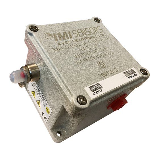
The IMI 685A mechanical switch is a shock sensitive mechanism for shutdown of the electric fan motor. This switch uses a patented linear adjustment mag- netic latch technology to ensure reliable operation. Pushing the reset button moves the tripping latch into a magnetically held position. A shock/vibration will move the magnet beyond this holding position, thus freeing the spring loaded tripping latch to transfer the contacts and shut down the machinery. -
Page 4: Installation
installation Before Installation • Stop the fan motor • Disconnect all electrical power to the fan motor • Make sure the machine cannot operate during installation by following proper lock-out tag-out procedures • Follow all cooling tower safety warnings • Read and follow all installation instructions Remove power before opening the cooling tower access door. -
Page 5: Field Wiring
installation VFD Safety/Run Circuit or Motor Starter Contactor Coil Circuit Sw 1 COMMON Sw 2 COMMON BMS Alarm Figure 1 Ground Field Wiring Typically this switch is used to shut off the tower fan motor and provide an alarm. The switch has two SPDT (single pole double throw) contacts operating in unison providing a contact closure or contact opening in the event of a trip. -
Page 6: Operation
operation Switch Setup The IMI switch is factory set to trip in the event of excessive shock/vibration within its capability and should not require adjustment. If adjustment is required, either the trip point needs to be adjusted or the switch is being subjected to an abnormally high vibration or shock. -
Page 7: Adjustment
operation A slight difference of 1/16" either way creates a large change in the trip Note point setting. Turning the adjustment screw clockwise increases the trip point making the switch less sensitive to shock. Turning the adjustment screw counter clockwise decreases the trip point making the switch more sensitive to shock. -
Page 8: Switches With Remote Reset
operation 1/4" GAP Figure 4 Gap Setting The factory setting is determined by a 1/4" gap measurement illustrated in Figure 4. Adjust the sensitivity screw clockwise or counter-clockwise to achieve the dimension shown. Switches with Remote Reset Option A switch with the remote reset option uses an internal electrical solenoid with a plunger to remotely reset the internal trip mechanism. - Page 9 operation The switch can be remotely reset after being tripped by applying the correct voltage across the reset terminal as shown below in Figure 5. There is no positive/negative polarity needed for the wiring. While Note the power is applied to the remote reset terminals, the switch cannot be tripped.
-
Page 10: Commissioning
operation 240 VAC Switch—A 240VAC, 50 Hz power supply is needed to remotely reset the switch by energizing a solenoid. Upon applying 240VAC to the solenoid, the unit will need 92mA to energize the remote reset coil. At standard ambient temperature, the solenoid has a 25% “on”... -
Page 11: Specifications
Specifications Model Reset Relay Contact Output Measurement Range Frequency Range 2396245 Manual external reset button Manual external reset button and 2442494 24 VDC remote reset solenoid Inertial 1-7 g pk One - DPDT form “C” 0 to 6000 cpm 0-68.7 m/s Manual external reset button and 15 amp at 120 VAC 0-100 Hz... - Page 12 IMI vibration switch U S E R M A N UA L SPX COOLING TECHNOLOGIES, INC. 7401 WEST 129 STREET Z0929039_A ISSUED 03/2017 OVERLAND PARK, KS 66213 USA COPYRIGHT © 2017 SPX CORPORATION In the interest of technological progress, all products are subject to design 913 664 7400 | spxcooling@spx.com and/or material change without notice.
Need help?
Do you have a question about the 685a and is the answer not in the manual?
Questions and answers