Advertisement
Table of Contents
- 1 Declaration of Conformity
- 2 Transportation , Handling and Storage
- 3 Installation and Connections
- 4 Safety Regulations
- 5 Preliminary Operations
- 6 Air Duct Connections
- 7 Water Connections
- 8 Wiring Diagrams
- 9 Maintenance
- 10 Electrical Connections
- 11 Yearly Maintenance
- 12 Heat Recovery
- 13 Refrigerant Circuit
- 14 Troubleshooting
- Download this manual
I
N
S
T
A
L
I
N
S
T
A
L
M
A
I
N
T
E
M
A
I
N
T
E
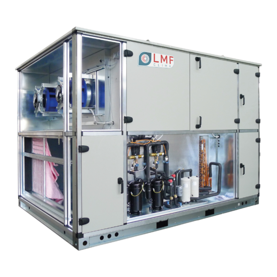
AIR TO AIR HEAT RECOVERY UNIT WITH BUILT-IN
INVERTER DRIVEN COMPRESSOR HEAT PUMP
MIUM0014_REV01_ HP_20151009-MIUM-ENG
L
A
T
I
O
N
L
A
T
I
O
N
N
A
N
C
E
N
A
N
C
E
SERIES HPH-HPR-HPS
,
O
P
E
R
,
O
P
E
R
M
A
N
U
A
M
A
N
U
A
A
T
I
O
N
A
A
T
I
O
N
A
L
L
N
D
N
D
1
Advertisement
Table of Contents

Subscribe to Our Youtube Channel
Summary of Contents for LMF Clima HPH series
- Page 1 AIR TO AIR HEAT RECOVERY UNIT WITH BUILT-IN INVERTER DRIVEN COMPRESSOR HEAT PUMP SERIES HPH-HPR-HPS MIUM0014_REV01_ HP_20151009-MIUM-ENG...
-
Page 2: Declaration Of Conformity
Dear Customer, Thank you for having purchased an LMF product. It is the result of many years of experience, research and has been Thank you for having purchased an LMF product. It is the result of many years of experience, research and has been Thank you for having purchased an LMF product. - Page 3 SYMBOLOGY ATTENTION DANGER HIGH RISK OF ELECTRIC SHOCK ATTENTION: AUTHORIZED PERSONNEL ONLY 1 – I NTRODUCTION pag. 4 2 - D IMENSIONS AND EIGHTS pag. 5 3 – T RANSPORTATION ANDLING AND TORAGE pag. 8 4 – I & C NSTALLATION ONNECTION pag.
- Page 4 1 - I NTRODUCTION Dear Customer, this heat recovery unit with built-in heat pump is designed and developed for civil, commercial and industrial applications and both allows the room air renewal and supplies tempered air with a sure energy saving. Unit must be used only for this purpose, LMF will not respond in case of different use of the unit.
- Page 5 2 – D IMENSIONS AND EIGHTS Packing dimensions The following table, referred to the figure, shows the characteristic dimensions of the series HPH and its accessories. S = Supply, E = Exhaust, R = Return F = Fresh air S = Supply, E = Exhaust, R = Return F = Fresh air 2185 2185 2515...
- Page 6 Packing dimensions The following table, referred to the figure, shows the characteristic dimensions of the series HPR and its accessories. S = Supply, E = Exhaust, R = Return F = Fresh air 2185 2185 2185 2185 2350 2350 2515 1030 1195 1360...
- Page 7 Packing dimensions The following table, referred to the figure, shows the characteristic dimensions of the series HPS and its accessories. S = Supply, E = Exhaust, R = Return F = Fresh air S = Supply, E = Exhaust, R = Return F = Fresh air 2185 2185 2515...
-
Page 8: Transportation , Handling And Storage
3 – T RANSPORTATION ANDLING AND TORAGE Packaging Each unit is put on bench and protected with cellophane film; the protection must remain intact until the moment of installation. The materials that are not mounted for technical motives are supplied in fitted packing fixed externally or internally to the unit. - Page 9 Before positioning please consider the overall dimensions and the technical space requirements of the system and the unit, electric and hydraulic connections and any air pipes/ducts or free passages. Neglecting these aspects may decrease performance and operational life of the unit and therefore increase the operating costs and maintenance.
-
Page 10: Installation And Connections
4 – I & C NSTALLATION ONNECTIONS Definitions CUSTOMER – The Customer is the person, activity or the society, that has bought or hired the unit, and intends to utilize the machinery for its intended use. USER / OPERATOR – The User or Operator is the actual person that has been authorized by the Customer to utilize the unit. -
Page 11: Preliminary Operations
Preliminary operations Check the perfect condition of the various components of the unit. • Control that contained within the packing, there are the installation accessories, and documentation. • Transport the packed section as close as is possible to the intended place of installation. •... -
Page 12: Air Duct Connections
Air duct connections IMPORTANT: IT IS IMPORTANT NOT TO PLACE IN OPERATION THE UNIT IF THE FAN OUTLETS ARE NOT DUCTED OR NOT PROTECTED BY A SAFETY NET ACCORDING TO THE ACTUAL REGULATION. The ducts must be correctly sized, in order to match unit external static pressure at duty airflow rate. •... -
Page 13: Wiring Diagrams
Electrical connections Before starting any operation, insure that the general power supply has been isolated. All the electrical connections must be protected at the source by the installer. Qualified personnel according to the supplied schemes must carry out the electrical connections at the control panel. Insure that the voltage and the frequency shown on the technical plate correspond to the connecting power •... -
Page 14: Yearly Maintenance
Monthly maintenance Air filters Each filter section can be entered through hinged side panel, provided with handle; once entered, filter can be removed by side after removing the vertical filter frame by an Allen key (1). This unit is equipped with soft bag filters; since they are not cleanable, check them monthly and replace them when dirty. For an automatic pressure drop limit control, installation of filter pressure switches is recommended. -
Page 15: Refrigerant Circuit
Refrigerant circuit Check the whole circuit in order to find possible gas leakage. In case of leakage, previously empty the circuit and recover the refrigerant. Remove the lower panel with built-in handles, fixed by panel locks, to enter compressor compartment. Fans Each fan section can be entered through hinged side panel, provided with handle. -
Page 16: Troubleshooting
Water coil (optional CCS section) By unscrewing and removing the panel on the opposite side to that of water connection, check that the heat exchange surface is clean and fins are in perfect condition. 8 – T ROUBLESHOOTING Failure searching and problem solving schedule The following table is for possible failures of air plant system;...
Need help?
Do you have a question about the HPH series and is the answer not in the manual?
Questions and answers