Table of Contents
Advertisement
Advertisement
Table of Contents

Related Manuals for MAHLE ACX1281


Summary of Contents for MAHLE ACX1281
- Page 1 MAHLE ACX1281 Operation manual A/C Service Units...
-
Page 2: Table Of Contents
2 | ACX1281 | Contents Commissioning Removing transportation packaging Symbols use Attaching handles In the documentation ACX1281 1.1.1 Warning notices—Structure and meaning 4 4.3.1 Setting language 1.1.2 Symbols in this documentation 4.3.2 Setting date and time On the product 4.3.3 Setting workshop data 4.3.4... -
Page 3: Acx1281 | 3
| ACX1281 | 3 ACX1281 | 3 Maintenance Maintenance interval Maintenance protocol Calibration of scales 8.3.1 Calibrating internal refrigerant bottle 8.3.2 Calibrating used oil bottle Calibration check Taring of Scales Replacing inline filters Vacuum pump 8.7.1 Changing vacuum pump oil 8.7.2... -
Page 4: Symbols Use
When a MAHLE product is handed over to another person, not only the Original instructions but also the KEY WORD – Nature and source of hazard! -
Page 5: Obligation Of Contractor
All data in this program is based—where possible—on manufac- The contractor is obliged to ensure that all measures geared turer and importer details. MAHLE does not accept liability for the towards the prevention of accidents, industrial diseases, labor- correctness and completeness of software and data; liability for related health risks are taken and measures towards making damage caused by faulty software and data is ruled out. -
Page 6: Safety Regulations
Welding and soldering are not permitted. immediately and rinse the area of skin affected with The ACX1281 unit should not be exposed to excess moisture generous amounts of water. or be operated in wet areas. -
Page 7: Refrigerant Identification Unit
The ACX1281 must always be transported in its operating For safety reasons it is advisable to use a residual current position. Never lay the ACX1281 on its side, as oil could then operated circuit breaker (rccb) with the following specifica-... -
Page 8: Safety Devices
ACX1281 features all the tached to the ACX1281. functions required for vehicle A/C service. Service door switch If the service door of the ACX1281 is removed, the ACX1281 stops all processes and starts service The following functions can be implemented: mode. -
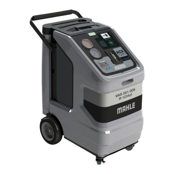
Page 9: Description Of Unit
Product description | ACX1281 | 9 ACX1281 | 9 Description of unit Fig. 2: Rear view Service door for used oil and vacuum pump oil Power supply cable inlet, circuit breaker Power supply cable Kick plate Flush device storage shelf / spare refrigerant bottle storage Fig. -
Page 10: Selection And Function Keys
Display and operating unit Status and warning light Various functions are assigned to the function keys in the Selection and function keys ACX1281 software. The functions of the keys are defined in the Refrigerant identifier menu line of the ACX1281 software. Printer... -
Page 11: Printer
(e.g. PVC folders). Fig. 7: Removing service door Fig. 5: Printer The built-in ventilation fan of the ACX1281 remains in opera- Cover tion when the ACX1281 switches to service mode to remove potentially flammable R1234yf refrigerant vapors which may 3.3.4 Service doors have accumulated in the housing during A/C service. -
Page 12: Scales For Oil And Refrigerant
12 | ACX1281 | Product description 3.3.5 Scales for oil and refrigerant 3.3.6 Service quick-release couplings There are various scales for checking the quantities of refriger- The service quick-release couplings are connected to the ant and used oil. service connections of the vehicle air conditioning system during A/C service. -
Page 13: Inline Filters
Refrigerant identification unit 3.3.7 Inline filters The service hoses are connected to the ACX1281 by way of the The refrigerant identification unit permits precise determination inline filters. The inline filters prevent the ingress of fine particles of the type of refrigerant as to prevent cross contamination by into the internal hydraulic circuit of the ACX1281. -
Page 14: Functional Description
14 | ACX1281 | Product description Functional description The refrigerant recovered from the air conditioning system passes through the combo filter to remove suspended particles and moisture. The purpose of the vacuum pump is to generate a vacuum in the air conditioning system which removes excess moisture and to detect possible leaks in the vehicle air conditioning system. -
Page 15: Commissioning
4. Rotate handle upwards and over top of the handle mounting When removing the packaging, use care to ensure there is no spacers. damage caused to the ACX1281 unit or any of the included accessories. Do not unplug any electrical connections and only have in- ternal components opened and repaired by trained customer service personnel. -
Page 16: Acx1281
A maximum of 30 characters can be entered. 1. Set the ACX1281 on a flat, vibration-proof surface. 2. Actuate the caster brake to stop the ACX1281 from rolling. Delete values previously entered with <C>. 3. Connect the power supply cable to the power supply. -
Page 17: Checking Type Of Connection Of External Refrigerant Bottle
An inadequate quantity may make efficient filling of the vehicle air conditioning system impossible. Also, if there is an insufficient quantity, the ACX1281 may not be able to operate efficiently. In the event of an excessive quantity, there may not be sufficient space for the refrigerant recovered from the vehicle air condi- tioning system. -
Page 18: A/C Service Preparation
(quick-release couplers) at the connection point Only new lubricant, as specified by the system manufacturer, to the A/C to minimize the introduction of air into the ACX1281 shall be installed in the MAC system. Lubricant removed from and to minimize the amount of refrigerant released while dis- the system and/or equipment shall be disposed of in accord- connecting the hoses. -
Page 19: Operation
1. Switch on the ACX1281. 2. Select "Vehicle A/C Service>>Refrigerant Identification". 1. Select "Settings>>My database". 3. Follow the menu prompting of ACX1281. 2. Select vehicle with . 3. Press . Getting message "Sample not OK", check for contamination 4. -
Page 20: Decontamination
1. Select “Maintenance>>Maintenance>> Decontamination” or process continues automatically after 3 failed identifications. 2. Switch off the ACX1281 unit. 3. Disconnect power cord from outlet. 4. Move unit outside. 5. Connect High and Low side couplers to the Parking/Flush adapter and open valves to equalize pressure. -
Page 21: Automatic A/C Service
Only after successful identification of refrigerant, service may begin on the vehicle. begin on the vehicle. The contamination of the service hoses on the ACX1281 unit The contamination of the service hoses on the ACX1281 unit can only be removed by following the decontamination proc- can only be removed by following the decontamination proc- ess (see Chapter 6.3.2). -
Page 22: Automatic/Manual Vehicle A/C Service Overview
ACX1281. If a PAG system is serviced and another vehicle with a POE system is to be serviced next, a flush routine must be performed to prevent a cross-contamination of the oils. -
Page 23: Draining Service Hoses
1. Select "Settings>>A/C service parameters". 2. Alter the parameters with the input keys. The ACX1281 performs a system leak test to check that none The parameters can be pre-set at the start of the correspond- of the components carrying refrigerant are leaking. Every 24 ing service phase in manual and automatic A/C service. - Page 24 • Check for clogging of service hoses. Service timeout • Check scales. 5001 RECHARGE: • Check for clogging of ACX1281. Service timeout. • Check whether the valves of the quick-release couplings are open. 5002 RECHARGE: • Perform Internal Cylinder Fill process.
-
Page 25: Troubleshooting | Acx1281 | 25
• Check scales A209 SHORT FLUSHING: • Check for clogging of service hoses. Charging unsuccessful. A302 EXTENDED FLUSHING: • Check for clogging of ACX1281. Service timeout. A303 EXTENDED FLUSHING: • Charge the internal refrigerant cylinder. Insufficient refrigerant quantity. A304 EXTENDED FLUSHING: •... -
Page 26: Refrigerant Identification Unit
26 | ACX1281 | Troubleshooting Refrigerant identification unit Error code Messages Action D000 Sample NOK • Move the unit away from sources of EMF or RFI such as radio transmitters and arc welders • Repeat refrigerant analysis D001 Air or gas reading was unstable •... -
Page 27: Maintenance
3. Attach the calibration check ball. Maintenance protocol 4. Select O. ” Calibration check completed. The ACX1281 stores various protocols which can be printed out. Getting message "calibration check failed", calibration check — Last 3 system service reports. should be performed again and if it still fails a second time, —... -
Page 28: Replacing Inline Filters
Adapter for connection Adapter for hoses Filter element Sealing ring Use the vacuum pump oil specified by MAHLE 1. Drain the service hoses. (part number 011 80070 00). 2. Disconnect the service hoses from the inline filters. 1. Place a container under the drain on back side of unit. -
Page 29: Combo Filter
Code entered when replacing the filter. It is not possible to operate the ACX1281 if the same code is re-used. It is advisable to 1. Check that gauges are both at 0 bar or less. If they are, skip keep a supply of filters in stock to avoid downtimes due to to step 3. -
Page 30: Software Update
8.11 Replacing white sample filter 8.12 Resetting the circuit breaker (Refrigerant identification unit) 1. Switch off the ACX1281 and unplug from receptacle. The need to replace the white sample filter may indicate oil 2. Allow unit to sit for a minute. -
Page 31: System Information
8.14 Service Report Disposal of LCD screen The ACX1281 unit tracks the quantity of refrigerant processed and requests a reset after January 1 of each calendar year. To perform this reset, the password required is "73738". -
Page 32: Technical Data
Feature Value/Range internal bottle of the ACX1281. The refrigerant oil collected Dimensions H x W x D 1016 x 580 x 840mm in the process is drained into the used oil bottle at the... -
Page 33: Notes
Notes | ACX1281 | 33 ACX1281 | 33 | 33 12. Notes © MAHLE... - Page 34 34 | ACX1281 | Notes © MAHLE...
- Page 35 Notes | ACX1281 | 35 ACX1281 | 35 | 35 © MAHLE...
- Page 36 Mahle Aftermarket Inc., Service Solutions 10 Innovation Drive York, PA 17402 717-840-0678 www.servicesolutions.mahle.com...
Need help?
Do you have a question about the ACX1281 and is the answer not in the manual?
Questions and answers