Table of Contents
Advertisement
Quick Links
Advertisement
Table of Contents

Summary of Contents for Hisarlar SB1150
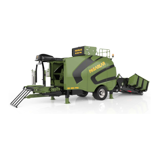
- Page 1 SILAGE BALER MACHINE USER AND MAINTENANCE MANUAL...
- Page 3 HİSARLAR SB1150 SILAGE BALER MACHINE USER AND MAINTENANCE MANUAL HSR_SB1150_00TR...
-
Page 4: Table Of Contents
0 TABLE OF CONTENTS Preface......................... 10 1.1 Technical Changes..................10 1.2 Part Delivery Process................11 GENERAL INFORMATION..................... 11 1.3 Safety Rules....................12 1.3.1 Safety Rules Applied by Users..................1.3.2 Operating of the Machine for Non-Design Purposes......... 1.3.3 Equipped and Trained Operator................1.3.4 Safety Accessories...................... - Page 5 2.5 Machine Identification Label..............25 2.6 Safety Labels....................26 TABLE OF CONTENTS....................30 3.1 Working Principle of the Machine............31 MACHINE INFORMATION.................... 31 3.2 Loading Tank....................32 Closing Side Covers........................Adjusting Balance Legs....................... Conveyor Belt and Tension Unit.................... 3.3 Transmitter Unit..................34 3.4 Netting Unit....................
- Page 6 0 TABLE OF CONTENTS 3.10 Hydraulic Control Valves..............40 3.11 Operator Screen..................41 3.11 Operator Screen..................42 3.11.1 Main Screen......................... 3.11.2 Main Screen........................3.11.3 Manual Operating Screen..................3.11.4 Setting Screen........................3.11.5 Tracking Screen....................... 3.11.6 Alarm Screen........................3.11.7 Alarm List..........................4.1 Operating of New Machines..............57 4.2 Pulling the Machine off to the Highway..........
- Page 7 Automatic Lubrication....................4.4.2 Placing the Net........................Net Feeding Mile......................Passing the Net through the Cylinders............4.4.3 Putting the Stretch Film....................4.4.4 Operating in Auto Mode....................MAINTENANCE INFORMATION................. 75 5.1 Operator Adjustment, Control and Maintenance......75 5.1.1 Electrical System Check....................Cable Check........................Sensors Check.........................
- Page 8 0 TABLE OF CONTENTS Automatic Lubricating Screen................Technical Specifications..................... Addition of Oil........................5.1.7 Manual Lubrication......................5.2 Periodical Maintenance Table............... 88 5.2.1 First Maintenance......................5.2.2 Daily Maintenance......................5.2.3 Two Days Maintenance....................5.2.4 Seasonal/Annual Maintenance................. 5.3 Authorized Services................. 90...
- Page 9 GENERAL INFORMATION TABLE OF CONTENTS....................10 Preface......................... 11 1.1 Technical Changes.................. 11 GENERAL INFORMATION.................... 11 1.2 Part Delivery Process................12 1.3 Safety Rules....................13 1.3.1 Safety Rules Applied by Users..................1.3.2 Operating of the Machine for Non-Design Purpose........1.3.3 Equipped and Trained Operator................1.3.4 Safety Accessories......................
-
Page 10: Preface
GENERAL INFORMATION Preface This user manual is designed to help you use your machine safely and efficiently. The manual must be read carefully before the machine is first used. This manual contains information about the machine's efficiency, first intervention in case of a possible failure and authorized services. -
Page 11: Part Delivery Process
GENEL BİLGİLER 1.2 Parça Gönderim İşlemi HİSARLAR CUSTOMER SERVICES Hisar District 1047th Str. No:2 26550 Tepebaşı Eskişehir / TÜRKİYE Tel: +90 222 411 24 30 Faks: +90 222 411 22 47 444 77 57 INFORMATION » Packing of the Parts The use of protective and safe materials in the packaging of parts prevents the parts from being damaged during transportation. -
Page 12: Safety Rules
SAFETY INFORMATION 1.3.Safety Rules 1.3.1.Safety Rules Applied by Users If any part of the machine is sent to the factory for repair or HİSARLAR machines are designed in a way that will not harm the fixation, you must use the address below. operator or third parties during use, and taking into account international safety guidelines. -
Page 13: Fire Probability
1.3.5.Fire Probability Please keep the equipment in accordance with the fire regulations in Check the pressure values your area, in the work area and in easily accessible places. Inform of the fire tubes at specific users of fire fighting and prevention issues or provide them with the time intervals. -
Page 14: Safety Information
SAFETY INFORMATION 1.4 Semboller INFORMATION » Informational Text The use of warning signs in Used to tell important additional information related to the subject. the manual in accordance with warnings, signs and texts increases the work safety. WARNING » Warning Text It is used to describe situations where damage may occur if attention is not paid. -
Page 15: Symbols
SAFETY INFORMATION 1.4.Symbols ELECTRICAL MAINTENANCE AND REPAIR » Electrical Maintenance and Repair It is used to describe that the described maintenance and repair work must be carried out by an electrician OPERATOR » Do It Yourself It is used to describe that the described maintenance, repair and control work must be performed by the operator. -
Page 16: Design Purpose Of The Machine
SAFETY INFORMATION 1.4.Symbols YÜKSEK SES » Loud Noise Used to describe situations when it is necessary to use ear protectors for the noise generated during operation. PROTECTIVE GOGGLES » Wear Protective Goggles Used to describe situations protective goggles should be used against the broken or flying pieces coming from the material being operated during the work. -
Page 17: Warranty Liability
SAFETY INFORMATION 1.6.Warranty Liability In this section, the warranty conditions to be applied in HİSARLAR product machines purchased, used or utilized for commercial and professional purposes except for the consumers specified in the Law no. 6502. 1. Warranty period starts from the machine's delivery date and lasts for two years or when 40,000 bales are finished (whichever comes first). -
Page 18: Warranty Information
WARRANTY INFORMATION 1.7 Garanti Dışı Durumlar 1. Any consumable material (filters, oils, liquids, light bulbs and all other consumab- le materials similar thereto). 2. Additional maintenance and lubrication and periodic operations required from the user. 3. Wear and tear due to normal usage (wear, tear and aging of all belts, light bulbs and lighting, signaling equipment, tire parts and all similar equipment and parts). -
Page 19: Warranty Expiring Conditions
WARRANTY INFORMATION 1.8.Expiration of Warranty 1. Use of machine contrary to the instructions in the user manual, 2. Repair, modification or dismantling of the machine at service stations not authorized by HİSARLAR. 3. Exceeding the load-capacity limit specified on the machine identification label. 4. -
Page 20: Machine Delivery Form
WARRANTY INFORMATION 1.10.Machine Delivery Form The Machine Delivery Form is a form signed by the customer in 3 copies after the delivery of the machine to the customer. One of the form copies is delivered to the customer. The second copy remains in the relevant seller. The third is kept at the after-sales service department of HİSARLAR. - Page 21 2 TEKNİK BİLGİLER TEKNİK BİLGİLER ..............2.1 Model Bilgileri ............... 2.2 Ölçüler ................. 2.3 Makine Yönü ..............2.4 Saklama Koşulları ............2.5 Makine Tanıtım Etiketi ........... 2.8 Güvenlik Etiketleri ............
-
Page 22: Technical Information
TECHNICAL INFORMATION 2.1 Model Bilgileri This User's Manual covers all of the following models. However, some parts, acces- sories and features used for customer demand and different power capacity values may not be available in your machine. 1150 General Length(Road 7505 Position) Length (Work... -
Page 23: Dimensions
TECHNICAL INFORMATION 2.2.Dimensions 3260 3258 6714 7505 2498 6780 7505 HSR_SB1150_00TR... -
Page 24: Machine Direction
TECHNICAL INFORMATION 2.3.Machine Direction In this manual, the terms FRONT, REAR, RIGHT and LEFT are used. These terms are explained below and are always used in the same sense. RIGHT LEFT FRONT FRONT: When the machine is viewed straight ahead, the surface where the stretching unit is seen. REAR: It is the surface where the bunker is seen when the machine is viewed straight ahead. -
Page 25: Storage Conditions
• Chassis No • Weight information are located. MODEL NAME SB 1150 MODEL YEAR 2018 CHASSISNUMBER Weight 8855 kg This product is produced by Hisarlar Mak. San. Tic. A.Ş. Address: Eskişehir-Bursa Highway 20. km. Çukurhisar/Eskişehir Tel: 0 222 411 24 30 HSR_SB1150_00TR... -
Page 26: Safety Labels
TECHNICAL INFORMATION 2.6. Safety Labels 1000 6586 1001 1197 1001 1243 1001 1244 1001 1247 1001 1248 1001 4176 1001 4175 1001 3980 1001 1282 1001 1281 1001 1280 1001 1251 1001 7212 BUNKER 1001 4220 1001 4221 1001 1250 1001 6459 Silage Baler Packing Machine User Manual... - Page 27 FRONT 1001 7202 DON’T PUT YOUR DON’T PUT YOUR HAND INTO THE HAND INTO THE OPERATING OPERATING MACHINE! MACHINE! MODEL NAME MODEL YEAR CHASSISNUMBER Weight This product is produced by Hisarlar Mak. San. Tic. A.Ş. Address: Eskişehir-Bursa Highway 20. HSR_SB1150_00TR...
- Page 28 TECHNICAL INFORMATION THIS PAGE IS INTENTIONALLY LEFT BLANK. Silage Baler Packing Machine User Manual...
- Page 29 3 MACHINE INFORMATION TABLE OF CONTENTS ..................32 3.1 Working Principle of the Machine............33 MACHINE INFORMATION................33 3.2 Loading Tank ....................34 Closing Side Covers......................Adjusting Balance Legs ..................... Conveyor Belt and Tension Unit ................... 3.3 Transmitter Unit ..................36 3.4 Netting Unit ....................
-
Page 30: Table Of Contents
TABLE OF CONTENTS 3.10 Hydraulic Control Valves ..............42 3.11 Operator Screen ..................43 3.11 Operator Screen ..................44 3.11.1 Main Screen ......................45 3.11.2 Main Screen ......................46 3.11.3 Manual Operating Screen ................47 3.11.4 Setting Screen ......................53 3.11.5 Tracking Screen ..................... -
Page 31: Working Principle Of The Machine
MACHINE INFORMATION 3.1 Working Principle of the Machine The minced material is loaded into the Loading Tank by means of a loader. The loaded material is then carried to the compression tank by the conveyor belt. The amount of material to be compressed is adjusted by the parameters set from the speed control sensors and the control panel. -
Page 32: Loading Tank
MACHINE INFORMATION 3.2 Loading Tank It is the part where the minced material is loaded with the aid of a loader. The height and gradient is adjusted with the balance legs and brought to the desired position and angle. Closing the Side Covers Loading tank side covers must be closed during transportation. -
Page 33: Adjusting Balance Legs
MACHINE INFORMATION 3.2 Loading Tank Adjusting the Balance Legs Use the bolts on the balance legs to adjust the position and angle of the l oading tank. A description is required for this process to be done safely. Conveyor Belt and Tension Unit In the loading unit, there is a conveyor belt that allows the material to slide from the ground. -
Page 34: Transmitter Unit
MACHINE INFORMATION 3.3 Transmitter Unit It is the section where the minced material is transported to the compression unit. There are straightening arms on the unit to ensure homogeneous feed of the material. 3.4 Netting Unit It is the section where the compressed bale is netted. Switch Assembly Net Feeding Shaft Shearing Blade... -
Page 35: Switch Group
MACHINE INFORMATION Switch Assembly Lighting Lamp Used to maket he netting unit be seen more clearly. It has a moving head. The angle can be set as desired. Magnetic Brake The unit in which the net roller is located and the shaft is magnetically braked. - Page 36 MACHINE INFORMATION Emergency STOP Switch It is used to stop the whole machine in case of an emergency To Stop the machine in an emergency; Press the Emergency STOP switch, After using the Emergency Stop switch, reset the switch to re-enable the machine.
-
Page 37: Bale Room
MACHINE INFORMATION 3.5.Bale Room The material flowing from the conveyor belt is poured into the compression tank. Baling is done in this tank. 3.6.Stretching Unit At the end of the baling process, the compression tank is opened and the bale comes to this unit to be stretched. -
Page 38: Control Panel
MACHINE INFORMATION 3.7.Control Panel The panel with all the electrical system of the machine. Main Switch The switch of the machine power supply. It has two positions. "0" Machine feed is not provided. (Machine does not operate) "1" Machine feed is provided. (Machine works) Emergency STOP Switch It is used to stop the machine in an emergency. -
Page 39: Balance Legs
MACHINE INFORMATION 3.8.Balance Legs They are hydraulic supported legs that allow the machine to stand on a flat surface. The legs are controlled by hydraulic control valves. 3.9.Weight Arrow and Its Hook It is a hydraulically extensible unit that is used for towing the machine tool. The weight arrow is controlled by hydraulic control valves. -
Page 40: Hydraulic Control Valves
MACHINE INFORMATION 3.10.Hydraulic Control Valves It is a hydraulically extensible unit that is used for towing of the machine. The weight arrow is controlled by hydraulic control valves. RIGHTER LEFT RIGHT LEFT REAR REAR FRONT WEIGHT ARROW BUNKER Silage Baler Packing Machine User Manual... -
Page 41: Operator Screen
MACHINE INFORMATION 3.11.Operator Screen The screen where the machine's settings can be viewed and modified. The operator display is not fixed. It can be moved all over the machine. ADET RESET Çıkış Ayarlar İzleme RESET Bunker Lamba ALARM Aç SAYFASI RULO FİLE HIZI Start... -
Page 42: Operator Screen
Access passwords should be given to authorized personnel during training following installation of the machine. If you have forgotten or lost your password, please contact the Hisarlar After Sales Services department. -
Page 43: Main Screen
MACHINE INFORMATION 3.11.1.Main Screen The screen where the machine's settings can be viewed and modified. The operator screen is n ot fixed. It can be moved all over the machine. NUMBER RESET Automatic Exit Settings Tracking RESET Bunker Turn On ALARM Auto The Lamps... -
Page 44: Main Screen
MACHINE INFORMATION 3.11.2.Main Screen POSE NAME EXPLANATION FUNCTION Bunker conveying belt start- stop Used to start the Bunker BUNKER conveying belt. “BUNKER OFF” appears on the button while the belt is running. It is used to activate all lamps on the machine. "LAMP OFF" on the Turn on-off the LAMP button when the lamps are on;... -
Page 45: Manual Operating Screen
MACHINE INFORMATION 3.11.3.Manual Operating Screen Makinenin tüm fonksiyonlarının manuel olarak çalıştırılabildiği ekrandır. Netting Open Blade Exit Engine START Chanel OPEN ALARM Chanel Blade PAGE Close OPEN CLOSE CLOSE Bunker Start Roll Carrier START START TRANSMITTER START Wrapping Packing START START Roll Spedd Scissors Ambalaj... - Page 46 MACHINE INFORMATION 3.11.3 Manuel Çalışma Ekranı POSE NAME EXPLANATION FUNCTON Scissors Open Used for opening BLADE OPEN the net scissors. BLADE Used for closing the net scissors Scissors Closed CLOSED Engine On-Off It turns on the NETTING net feeding ENGINE engine.
- Page 47 MACHINE INFORMATION 3.11.3 Manual Operating Screen POSE NAME EXPLANATION FUNCTON Starting Engine Used to start OPEN the netting engine. CLOSE Engine Stop Used to stop the netting engine. Bunker conveying belt On-Off Used to turn on the Bunker BUNKER Conveying Belt. START “BUNKER OFF”...
- Page 48 MACHINE INFORMATION 3.11.3 Manuel Operating Screen POSE NAME EXPLANATION FUNCTON Conveyor On-Off Used to turn on the conveying TRANSMITTER belt carryng START the material coming from the Bunker Compression ROLL tank roll OnOff It is used to operate the rolls of the compression tank. START Feedback conveyor...
- Page 49 MACHINE INFORMATION 3.11.3.Manual Operating Screen POSE NAME EXPLANATION FUNCTON Wrapping Unit Start Stop WRAPPING It is used to START operate the stretching unit. Used to adjust the wrapping speed of the Stretching Unit. Wrapping Unit SPEED speed adjustment (Minimum value: 5, Maximum value: 100) SCISSORS Used to lift up the scissors of Stretching Unit.
- Page 50 MACHINE INFORMATION POSE NAME EXPLANATION FUNCTON Lifting up the platform Used for lifting the packing PACKING platform. (Up) Platform rises up as long as the button is held down. PACKING It is used to lower the packing platform. The platform goes Lowering Down (Down) down as long as the button is held down.
-
Page 51: Setting Screen
MACHINE INFORMATION 3.11.4.Setting Screen The screenshowing the operating values of the machine in automatic operating mode and enabling adjustments Transmitter Net Release Exit Auto Speed Number Net Wrapping Transmitter Current Slow Speed Number Adjustments Wrapping Passive Bunker OFF Start Speed And Sensor Time Wrap... - Page 52 MACHINE INFORMATION POSE NAME EXPLANATION The bale, which comes out of the compression tank and falls on the packing roll, is started to be stretched. The stretch wrapping arms rotate WRAPPING START slowly first, then accelerate. This parameter specifies the value at which SPEED the stretch arms turn slowly.
-
Page 53: Tracking Screen
MACHINE INFORMATION 3.11.5.Tracking Screen A screen that allows the machine to be controlled technically during operation. The status of the sensors positioned according to the operating principle is checked from this screen. Exit Plc Inputs X20-Panel X30-Wrapp ng X40-Bale s Out X50-Net WrapperWrapp ng Emergency Stop... -
Page 54: Alarm List
MACHINE INFORMATION 3.11.7 Alarm Listesi Failures occurring during operation are displayed as a list in the alarm screen. ALARM EXPLANATION MAIN ENGINE SPEED CONTROL DEVICE B001 FAILURE HYDRAULIC ENGINE THERMIC FAILURE B002 BUNKER MOT THERMIC FAILURE B003 TRANSMITTER MOT THERMIC FAILURE B004 CONVEYING MOT THERMIC FAILURE B005... - Page 55 4 OPERATING INFORMATION 4.1 Operating of New Machines ..........4.2 Pulling the Machine off to the Highway ......4.3 Towing the Machine ............. 4.3.1 Dismantling Bunker Channel ..........4.3.2 Closing Bunker Side Covers ..........4.3.3 Pulling the Bunker to Towing Position ......
-
Page 56: Operating Information
OPERATING INFORMATION THIS PAGE IS INTENTIONALLY LEFT BLANK. Silage Baler Packing Machine User Manual... -
Page 57: Operating Of New Machines
OPERATING INFORMATION 4.1.Operating of New Machines New machines are run for a certain period of time prior to switching to full capacity. For this reason, do not operate the machine at the highest speed until the first 20 hours of operation or 600 bales are made. -
Page 58: Pulling The Machine Off To The Highway
OPERATING INFORMATION 4.2.Pulling the Machine off to the Highway Silage Baler Packing Machines are designed to be transported by towing by a tractor. For this reason, the speed l imits in the following table should be applied. Outside Settlement (km) Within Highways Settlement... -
Page 59: Towing The Machine
OPERATING INFORMATION 4.3.Towing the Machine The follo wing steps are required for pulling the machine. Determining the suitability of the tractorto pull the machine. Dismantling the Bunker channel Closing the Bunker side covers Positioning the Bunker in towing position Use a tractor with Attaching the weight arrow and its hook to the tractor MINIMUM 65 HP, 4X4... -
Page 60: Closing Bunker Side Covers
OPERATING INFORMATION 4.3.2.Closing Bunker Side Covers Remove the connecting bolts of the bunker side covers and fold the covers inward. Save the side cover fixing bolts you disassemble. Side covers are he avy. Gently tilt the cover with bolt removed. Do not let the cover fall freely. -
Page 61: Weight Arrow And Its Hook
OPERATING INFORMATION 4.3.4.Weight Arrow and Its Hook The weight arrow, which is used for drawing the machine and hydraulically extensible, is controlled by hydraulic control valves. Make sure that there is no object in front of the arrow while making it move move forward. -
Page 62: Closing Balance Legs
OPERATING INFORMATION 4.3.5.Closing the Balance Legs The legs are controlled by hydraulic control valves. Move the control arms (right rear- left rear- right front- left front) in the same time so that the machine balance is not distorted. RIGHT REAR LEFT REAR Move the hydraulic valves slowly... -
Page 63: Pulling The Hydraulic Valves To The Towing Position
OPERATING INFORMATION 4.3.7.Pulling the Hydraulic Valves to the Towing Position Switch the valves (2 pcs) in the hydraulic valve access section on the left side of the machine to off position. The valves are open when in parallel with the pipe to which they are connected and closed when in the upright position. -
Page 64: Connecting The Tractor Signalling Cable
OPERATING INFORMATION 4.3.8.Connecting the Tractor Signalling Cable When the machine is towed to the road, the tractor signaling system is transferred to the machine to ensure traffic safety. Connect one end of the connecting cable in the tool kit, and the other end to the machine. -
Page 65: Signalization Control
OPERATING INFORMATION 4.3.9.Signalization Check The signaling system of each tractor brand may vary. For this reason, make sure that the entire signaling system works correctly after you connect the machine to the tractor. HSR_SB1150_00TR... -
Page 66: Last Controls Before Towing
OPERATING INFORMATION 4.3.10. Last Controls Before Towing Make sure that all covers are closed. Make sure that the joiner pin of the towing pin is installed correctly. Make sure that the hydraulic valves are brought to the towing position. Try the tractor signals one by one to make sure that all signals match the machine. -
Page 67: Operating The Machine
Max. Kg Strength the machine to be out of warranty. available available UV Katkısı Please consult Hisarlar After Sales Services unit for different Stretch Film Technical Specifications materials. Stretch Film Technical Unit 50 cm 75 cm... -
Page 68: Placing The Net
OPERATING INFORMATION 4.4.2.Placing the Net INFORMATION » Operation Preparation For this process step; The machine should be in operation, Stair platform should be open, The operator screen must be connected to the machine. Along with these, go to the top of the machine by taking the operator's screen to your side. -
Page 69: Net Feeding Mile
Netting Feed Shaft (1) In order to remove the feed shaft (2) Lift up the tensioner arm from its place by removing the tension spring again. Remove the netting feed shaft first by pulling it up and then towards you. (3) Install the netting roll onto the feed shaft and fasten. -
Page 70: Passing The Net Through The Cylinders
OPERATING INFORMATION Passing the Net through the Cylinders Pass the net through the cylinders as shown below and hang down below the Blade. INFORMATION Do the net opening » Perform the open the net process from the operator's screen before performing this operation. To do this, first take the machine to Manual mode. -
Page 71: Putting The Stretch Film
OPERATING INFORMATION 4.4.3.Attaching the Stretch Film Depending on the material to be processed in the machine, both 50 cm and 75 cm stretch film can be used. Within the tool set, there is a suitably sized shaft for both. INFORMATION »... -
Page 72: Operating In Auto Mode
OPERATING INFORMATION 4.4.4.Operating in Auto Mode WARNING » Hidrolik Valfler Make sure that the hydraulic valves are in the operating position before operating the machine. Operation of the machine when the hydraulic valves are in the pull position can cause significant damage to the hydraulic engines of the machine. - Page 73 MAINTENANCE INFORMATION MAINTENANCE INFORMATION ............75 5.1 Operator Adjustment, Control and Maintenance ... 75 5.1.1 Electric System Check ............76 Cable Check ....................76 Sensors Check ....................76 Control Panel Check .................... 76 Operat or Screen Check ................. 76 5.1.2 Tire Check ................ 77 Tire Rotation .....................
- Page 74 MAINTENANCE INFORMATION 5.2 Periodic al Maintenance Table ..........88 ................88 5.2.1 First Maintenance ................88 5.2.2 Daily Maintenance Two Days Maintenance ………………........……… 5.2.3 ………………..... 5.2.4 Seasonal / Annual Maintenance 5.3 Authorized Services ............90 Silage Baler Packing Machine User Manual...
-
Page 75: Maintenance Information
The simple setting, inspection and maintenance procedures described in this manual should only be performed by operators who have been trained by the Hisarlar in this regard. The simple setting, inspection and maintenance procedures described in this manual should only be performed by operators who have been trained by the Hisarlar in this regard. -
Page 76: Electrical System Check
MAINTENANCE INFORMATION 5.1.1.Electrical System Check Regularly check the electrical system of the machine. The electrical system consists of wiring, sensors, control panel and operator screen. Cable Check Check all cables used on the machine for damage, wear and tear. Especially in the season when machine is not working, cabling can be damaged by rodents according to the storage conditions of the machine. -
Page 77: Tire Check
MAINTENANCE INFORMATION 5.1.2.Tyre Check There are two tires on the machine. It may be that the machine is moved or transported even though the tires do not function while the machine is running. For this reason, the condition of the tires should be checked regularly. Tyre Rotation Change the location of the tires on the machine at the beginning of each season. -
Page 78: Chain Check
MAINTENANCE INFORMATION 5.1.3.Chain Check Bale Room Chains The chain-to-gear system used to move the bale room cylinders has a spring tension mechanism. For this reason, there is no need to adjust the chain tension. However, check the status of the chains on a daily basis. Change the chain if wear and damage are detected at the connection points. -
Page 79: Loader Conveyor Chain
MAINTENANCE INFORMATION Max. 5 mm Loader Conveyor Chain The loader conveyor chain tension can change as the machine is used. For this reason, check the chain tension daily. To check the chain tension, stop the machine and press the emergency stop button. -
Page 80: Hydraulic Oil Tank
MAINTENANCE INFORMATION 5.1.4.Hiydraulic Oil Tank Filler Hole Main Filter Drain Plug Suction Filter Temperature- Level Indicator Oil Level Check Check the hydraulic oil level daily. Hydraulic oil tank capacity is 90 lt. INFORMATION » Oil Level Check the hydraulic oil level only when the machine is not running. If you have just stopped the machine, wait 10 minutes for the oil to reach its own level. -
Page 81: Belt Adjustments
MAINTENANCE INFORMATION 5.1.5.Belt Adjustment The belt tension and settlement can change as the machine is used. For this reason, check both the belt tension and the placement of the belts on the cylinders on a daily basis. To check the belt tension, stop the machine and press the emergency stop button. Packing Belt Tension The belt tension should be such as to completely cover the roll surface. -
Page 82: Bale Room Belt Adjustments
MAINTENANCE INFORMATION Bale Room Belt Adjustments Under normal conditions the roll belt should be exactly centered on the cylinders. However, the belts may slip during operation. In such a case, the belt needs to be re-centered. In order for the belt to be re-centered, the bearing bed opposite the side of the slided belt must be raised. -
Page 83: Bale Room Tension Spring Adjustments
MAINTENANCE INFORMATION Bale Room Tension Spring Adjustment The compression force required in the bale chamber is provided through the springs on both sides of the machine. The springs must be completely closed when the bale room is closed (no load). In other words, the spring must remain free when the bale room is closed. -
Page 84: Automatic Lubricating Screen
MAINTENANCE INFORMATION Automatic Lubrication Screen The operating parameters of the automatic lubricating system are set in the factory. Delivered ready for use in the field. For this reason, do not change the lubrication parameters. Function Symbol Description SCREEN Shows values and processing steps. WAITING LAMP It lights up on waiting times It lights up in Lubrication time (when... -
Page 85: Technical Specifications
MAINTENANCE INFORMATION Technical Specifications Explanation Feature Fluid Exit Speed 2,5 cm /min Operating Pressure Maximum 300 Bar Operating Temperature -25 + 75 ° C Fluid Used Grease at level of NILGI 2 Reservoir Storage 6 kg Weight (When Grease is 11 kg full ) Start Amper e... -
Page 86: Manual Lubrication
MAINTENANCE INFORMATION 5.1.7.Manual Lubrication The lubrication points that automatic lubrication does not reach are shown below. The indicated dots are shown on one side of the machine. The symmetrical lubrication points must be subjected to manual lubrication in the same way. Silage Baler Packing Machine User Manual... - Page 87 MAINTENANCE INFORMATION Manual lubrication points should be greased during working periods of 600 bales / 2 days. HSR_SB1150_00TR...
-
Page 88: Periodical Maintenance Table
Failure to perform timely and complete periodic maintenance will result in termination of the machine's warranty status. 5.2.1.First Maintenance After the first 1000 bales from the machine's installation, machine maintenance should be performed by Hisarlar After Sales Services Team. Interval Part Process to be performed... -
Page 89: Two Days Maintenance
MAINTENANCE INFORMATION Process to be Explanation Section Interval performed Check the joint points of the packing belt. Belt joint Daily / 300 Strecthing Unit Make sure that the joining pin is locations Bales not damaged. Perform a functional check of Daily / 300 Stretching Unit Scissors check... -
Page 90: Seasonal/Annual Maintenance
5.3 Authorized Services Hisarlar Makine After Sales Services Unit has a wide network of authorized services both inside and outside of Turkey. You can visit our website for up-to-date service information. HİSARLAR CUSTOMER SERVICES Hisar District 1047th Str.
Need help?
Do you have a question about the SB1150 and is the answer not in the manual?
Questions and answers