Table of Contents
Advertisement
Quick Links
Advertisement
Table of Contents

Subscribe to Our Youtube Channel
Related Manuals for OKPOS Optimus

Summary of Contents for OKPOS Optimus
- Page 1 Optimus Service Manual OKPOS...
-
Page 2: Table Of Contents
Contents Before Using the Product LCD Customer Display COM and SATA sub-board Read this first Turning the SYSTEM On/Off Safety Information Turning On Information on Copyrights Turning Off Overview System Disassembly What’s in the Box Disassembling the System ➊ Removing the cover System Overview ➋... - Page 3 Setting Up the Touch Screen Touch Control B/D Specifications Setting Up the Card Reader Board Layout Running the setup program COM and SATA Sub-board (optional) Track setting Sound setting Board Layout I/Button setting Connector Descriptions Error code setting Setting Up the VFD Cable Pin Assignment Setting Up the LCD Customer Display LVDS Cable...
-
Page 4: Before Using The Product
The basic drivers and utilities that come with your system are subject to change. ● OKPOS assumes no responsibility for damages resulting from a use of the product that is not ● approved by OKPOS, or failure to follow the precautions and instructions provided in this User Manual. -
Page 5: Information On Copyrights
OKPOS Co., Ltd. OKPOS and Optimus are registered trademark of OKPOS Co., Ltd. ● Windows 7/10 is a registered trademark of Microsoft. -
Page 6: Overview
If any of the above is missing, please contact the customer center. ⦁ Only use devices with this system that have been supplied or approved by OKPOS. If you use a device supplied ⦁ by another provider that is not approved, your system may malfunction or not work. -
Page 7: System Overview
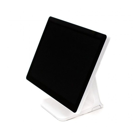
System Overview Front Touch display panel (touch LCD) Stand Overview | System Overview... -
Page 8: Rear And I/O Ports
Rear and I/O ports I/O port cover Power button Two USB ports Stand rear cover Cable hole COM2 port LAN port COM1 port Four USB ports Power (12V DC-IN) jack Speaker jack Power (12V DC-OUT) jack VGA port COM4 port COM3 port Overview | System Overview... -
Page 9: Adjusting Lcd Angle
Adjusting LCD Angle You can tilt the LCD to achieve the optimum viewing angle. The angle can be adjusted within 45 degrees up/down. Adjust the tilt of the LCD for your convenience. CAUTION: Do not put sharp objects on the surface of the LCD, and never spray cleaner directly onto the display. ⦁... -
Page 10: Installation
Installation Connecting Peripherals Removing the I/O port cover Using your fingers, push and hold the two points marked PUSH on the I/O port cover, then slide the cover up. -
Page 11: Removing The Stand's Rear Cover
Removing the stand’s rear cover Hold the lower side of the stand’s rear cover and pull it away from the stand. Connecting peripheral devices Installation | Connecting Peripherals... -
Page 12: Connecting The Power Cord
Connecting the power cord Plug the power cord into the power jack on the I/O panel and then plug the other end of the power cord into an appropriately grounded electrical outlet. Replacing the I/O port cover Make sure that all of the connected cables are arranged through the cable hole position of the I/O port cover so that they will not be pinched when you replace the cover. -
Page 13: Replacing The Stand's Rear Cover
Replacing the stand’s rear cover Make sure that all cables are arranged inside the cable path of the stand so that they will not be pinched when you close the stand’s rear cover. Align the two latch pins on the upper side of the cover with the stand latch holes, and press the lower side of the cover firmly into place. -
Page 14: Installing Optional Devices
Installing Optional Devices Card reader (IC & MSR) Installing the card reader To install the card reader, follow these steps: Place the touch LCD panel side down on a soft, flat surface. (Be careful not to damage the touch LCD panel.) To remove the dummy cover, press the marked point and slide the dummy cover slightly, and then lift it up. - Page 15 Align the two latch pins on the card reader with the back cover holes and press the card reader down firmly into place. Tighten the two screws. Removing the card reader You can remove the card reader by following the steps in the installation procedure in reverse order. Installation | Installing Optional Devices...
-
Page 16: Vfd
Installing the VFD To install the VFD, follow these steps: Remove the I/O port cover by following the instructions in “Removing the I/O port cover“ on page 10. Detach the plate on the I/O port cover to make space for installing the VFD. NOTE: Completely remove the plate, ensuring that no sharp parts remain. -
Page 17: Lcd Customer Display
Connect the RJ-45 cable of the VFD to the COM3 port. Replace the I/O port cover by following the instructions in “Replacing the I/O port cover“ on page 12. After installing the VFD, change the BIOS setting by following the instructions in “Setting Up the VFD“... - Page 18 Detach the plate on the I/O port cover to make space for installing the LCD customer display. NOTE: Completely remove the plate, ensuring that no sharp parts remain. There is the risk of injuring yourself if the ⦁ sharp edges are not completely removed. Place the LCD customer display and tighten it with two thumbscrews.
- Page 19 Connect the power cable of the LCD customer display to the power (12V DC-OUT) jack. Connect the VGA cable of the LCD customer display to the VGA port. Replace the I/O port cover by following the instructions in “Replacing the I/O port cover“ on page 12.
-
Page 20: Com And Sata Sub-Board
COM and SATA sub-board Installing the COM and SATA sub-board To install the COM and SATA sub-board, follow these steps: Remove the system cover by following the instructions in “➊ Removing the cover“ on page 22. Connect the COM and SATA sub-board to the COM and SATA header on the main board, and tighten the two screws. -
Page 21: Turning The System On/Off
Turning the SYSTEM On/Off Turning On Turn on the power of the peripheral devices connected to the system. Press the power button on the lower right side of the back of the system. Turning Off Close all the applications currently running. Windows 7: Click Start ➜... -
Page 22: System Disassembly
System Disassembly Disassembling the System ➊ Removing the cover To remove the system cover, follow these steps: Turn off the system and peripheral devices. Remove the I/O port cover by following the instructions in “Removing the I/O port cover“ on page 10. - Page 23 NOTE: This step is optional. If you do not need to disassemble the stand unit, go to step 7. ⦁ To disassemble the stand, remove the screws and separate the metal frame from the plastic case. ⦁ Remove the card reader or dummy cover. [When a card reader is installed] ①...
- Page 24 ② Remove the RJ-45 cable from the main board. [When a dummy cover is installed] To remove the dummy cover, hold one end of the dummy cover and lift up slightly, then pull it out. System Disassembly | Disassembling the System...
-
Page 25: ➋ Removing The Com And Sata
Remove the eight screws, slide the back cover slightly, and lift up the back cover. ➋ Removing the COM and SATA sub-board (optional) To remove the optional COM and SATA sub-board, follow these steps: Remove the screws fixing the COM and SATA sub-board. Remove the COM and SATA sub-board from the main board, and separate it from the chassis. -
Page 26: ➌ Removing The Main Board
➌ Removing the main board To remove the main board, follow these steps: Remove all cables (LVDS, speaker, touch cable, etc.) from the main board. Remove the screws and separate the main board from the chassis. System Disassembly | Disassembling the System... -
Page 27: ➍ Removing The Touch Panel
➍ Removing the touch panel To remove the touch panel, follow these steps: Remove the screws fixing the touch panel module. Separate the touch panel module. System Disassembly | Disassembling the System... -
Page 28: ➎ Removing The Lcd Module
➎ Removing the LCD module To remove the LCD module, follow these steps: Remove the screws fixing the LCD module. Separate the LCD module. System Disassembly | Disassembling the System... -
Page 29: Re-Assembling The System
Re-assembling the System You can assemble the system by following the steps in the disassembly procedure in reverse order. System Disassembly | Re-assembling the System... -
Page 30: Components Replacement
Components Replacement Replacing the M.2 SSD To replace the M.2 SSD, follow these steps: Turn off the system and peripheral devices. Remove the I/O port cover by following the instructions in “Removing the I/O port cover“ on page 10. Remove the stand’s rear cover by following the instructions in “Removing the stand’s rear cover“ on page 11. - Page 31 Install the new M.2 SSD card and tighten the screw. Replace the card reader or dummy cover. Connect the power cord and all cables to the system. Replace the I/O port cover by following the instructions in “Replacing the I/O port cover“ on page 12.
-
Page 32: Replacing The Memory Module (Ram)
Replacing the memory module (RAM) To replace the memory module, follow these steps: Remove the system cover by following the instructions in “➊ Removing the cover“ on page 22. Pull the clips on both sides of the memory slot outward to release the installed memory module. - Page 33 Insert the new memory modules into the open slots at a 30-degree angle, and press down until both clips engage and click into place. Replace the system cover by following the instructions for removal in reverse order. System Disassembly | Components Replacement...
-
Page 34: Replacing The Cmos Battery
Replacing the CMOS battery To replace the CMOS battery on the main board, follow these steps: Remove the system cover by following the instructions in “➊ Removing the cover“ on page 22. Locate the CMOS battery on the main board and gently press the retaining clip on the CMOS battery socket. -
Page 35: Replacing The Ssd (Optional)
Replace the system cover by following the steps for removal in reverse order. Replacing the SSD (optional) To replace the optional SSD, follow these steps: Turn off the system and peripheral devices. Remove the I/O port cover by following the instructions in “Removing the I/O port cover“ on page 10. - Page 36 Replace the SSD. Insert the SSD module into the slot and tighten the thumbscrew. Connect the power cord and all cables to the system. Replace the I/O port cover by following the instructions in “Replacing the I/O port cover“ on page 12.
-
Page 37: Application Programs
Application Programs Drivers All drivers are located in D:\OKPOS\DRIVER. All drivers are pre-installed on your system. If you need to install a driver, you can install it using the driver installation files, which can be found in these folders. Windows 7 Drivers Windows 8 &... - Page 38 [Windows 7] Turn on your system. Select Start ➜ Control Panel ➜ Tablet PC Settings. ➋ ➌ ➊ When the Tablet PC Settings screen appears, click Calibrate in the Display tab. Application Programs | Setting Up the Touch Screen...
- Page 39 Calibrate your touch screen by following the on-screen instructions. [Windows 10] Turn on your system. Select Start ➜ Control Panel ➜ Tablet PC Settings. ➋ ➌ ➊ Application Programs | Setting Up the Touch Screen...
- Page 40 When the Tablet PC Settings screen appears, click Calibrate in the Display tab. Calibrate your touch screen by following the on-screen instructions. Application Programs | Setting Up the Touch Screen...
-
Page 41: Setting Up The Card Reader
Setting Up the Card Reader After connecting the card reader, run the MRMSetter program to setup the card reader. Running the setup program Double-click the MRMSetter icon on the desktop. ➊ ➐ ➋ ➌ ➍ ➎ ➏ ➊ Read Data: Loads the previous setting values. ➋... -
Page 42: Track Setting
Track setting You can set the track. Select the track, input Start Code and End Code, and select Enter. Click Write Data and check the WRITE OK! message. Sound setting You can set the alarm for the card reading failure. Click the ON button for Sound. -
Page 43: I/Button Setting
I/Button setting You can set the I/Button. Select I/Button and Enter. Click Write Data and check the message. If there is no error, click WRITE OK! Error code setting You can set the Error Code. Click the ON button for Error. Click Write Data and check the message. -
Page 44: Setting Up The Vfd
Setting Up the VFD To setup the VFD, please follow these steps: After powering on the system, press [Del] to enter the System Setup screen. Go to the Advanced menu. Select Super IO Configuration. Select Serial Port 3 Configuration. Aptio Setup Utility - Copyright (C) 2017 American Megatrands, Inc. Advanced Super IO Configuration Set Parameters of Serial Port 3... - Page 45 Select Serial Port Voltage and choose +5V from the option list. Aptio Setup Utility - Copyright (C) 2017 American Megatrands, Inc. Advanced Serial Port 3 Configuration Select Serial Port Voltage Serial Port [Enabled] Serial Port Voltage [RI#] Device Settings IO=3E8h ; IRQ=6 ; Change Settings [Auto] Serial Port Voltage ���� : Select Screen +12V ���� : Select Item Enter : Select +/- : Change Opt.
-
Page 46: Setting Up The Lcd Customer Display
Setting Up the LCD Customer Display To set up the LCD Customer Display, please follow these steps: Turn on your system. Click Intel ® HD Graphics on the task bar and select Graphics Properties…. ➋ ➊ ® When the Intel HD Graphics Control Panel screen appears, select Display. - Page 47 Choose the display mode in the Select Display Mode menu. After finishing the other settings, click Apply. To keep the changes you have made to the settings, click Yes. Application Programs | Setting Up the LCD Customer Display...
-
Page 48: System Setup (Bios)
System Setup (BIOS) For System Set up, setup only the items that you need. Note that incorrect settings of Setup items could result in a system malfunction. Entering Setup After powering on the system, press [Del] to enter the System Setup screen. BIOS action keys Function key Command... -
Page 49: Main Menu
Main menu This menu reports processor and BIOS information, and is for configuring the system date and time. Features Options Description BIOS Information No options Displays the BIOS information. CPU Configuration No options Displays the processor configuration. System Date Month, day, and year Specifies the current date. -
Page 50: Advanced Menu
Advanced menu This menu is for setting advanced features that are available through the chipset. Features Options Description ACPI Settings ⮩ Enable Hibernation Enabled Enables or disables the system’s ability to ● Disabled Hibernate (OS/S4 Sleep State). This option may ●... - Page 51 Features Options Description Power Button Control ⮩ Restore AC Power Power Off Determines the mode of operation when your ● Loss Power On system resumes after an AC power loss. ● Last State ● CPU Configuration ⮩ Socket 0 CPU No options Displays the CPU information of the specified Information...
- Page 52 Features Options Description USB Configuration ⮩ USB Devices - Legacy USB Support Enabled Enables or disables the support for USB devices ● Disabled on legacy operating systems. ● - XHCI Hand-off Enabled This is a workaround for OSes that lack XHCI ●...
-
Page 53: Chipset Menu
Chipset menu You can change the values for the chipset to optimize system performance. Features Options Description North Bridge ⮩ Graphics Configuration - DVMT Pre-Allocated 64 MB Select the fixed amount of system memory ● 128 MB allocated to the integrated graphics device ●... -
Page 54: Security Menu
Features Options Description South Bridge ⮩ Azalia HD Audio - Audio Controller Enabled Enables or disables the Azalia HD Audio ● Disabled controller. ● ⮩ USB Configuration - USB 2.0 (EHCI) Enables or disables USB 2.0 support. Support - USB Port 1/2 Enables or disables the USB port 1/2. - Page 55 3. On the following screen, enter the same password again and press the [Enter] key. Confirm New Password 4. This will complete the password setup. Changing the password 1. Go to Administrator Password (or User Password) when you want to change the password, and then press the [Enter] key.
-
Page 56: Boot Menu
3. On the following screen, enter nothing and press the [Enter] key. Create New Password 4. When you get a message that says “Clear Old Password, Continue?” select Yes and press the [Enter] key. 5. This will complete deletion of the password. Boot menu This menu is for setting the boot sequence. -
Page 57: Save & Exit Menu
Save & Exit menu This menu is for exiting the Setup program, saving changes, and loading and saving defaults. Features Description Save & Exit ⮩ Save Changes and Reset Exits and saves the changes to CMOS RAM. ⮩ Discard Changes and Reset Exits without saving any changes made in Setup. -
Page 58: Hdd Recovery
HDD Recovery WARNING: The hard disk recovery process erases all of the data and programs that you installed on your hard disk. After a ⦁ hard disk recovery, you must reinstall any software that was not originally installed at the factory. Be sure to backup your own data before running the recovery process. -
Page 59: System Boards
System Boards Main Board Mainboard layout... - Page 60 System fan header Realtek RTL 8111F LAN controller LVDS header ITE IT8766E-I super I/O controller Front panel header CMOS battery USB ports COM and SATA connector M.2 SATA2 2260/2280 SSD socket Clear CMOS jumper Power button Buzzer Memory socket USB 8 pins FPC connector for touch Realtek Codec ALC662 audio controller Speaker header I/O ports...
-
Page 61: I/O Ports Of Main B/D
I/O Ports of Main B/D R_USB R_USB DC_IN1 LAN1 RJ_COM1-4 VGA1 DC_OUT1 DC-12V Input Connector DC-12V Output Jack (3.5 Ø, Max. 2A) Definition +DC 12V +12V DC_IN +12V DC_IN Jumper Settings The illustration shows how to set up jumpers. When the jumper cap is placed on pins, the jumper is "close", if not, that means the jumper is "open". -
Page 62: Headers And Connectors
※ Clear CMOS Procedures: 1. Remove AC power line. 2. Set the jumper to "Pin 2-3 close". 3. Wait for five seconds. 4. Set the jumper to "Pin 1-2 close". 5. Power on the AC. 6. Load Optimal Defaults and save settings in CMOS. Headers and connectors Front panel header (F_PANEL1) This 10-pin header includes HD LED, Power LED, Reset, PWR connection. - Page 63 LVDS header (LVDS1) This connector supports 18/24 bit dual-channel panels. Definition Definition +12V +12V +12V +12V +12V +3.3V LVDS_BKL_ADJ LVDS_BKL_EN LVDS_A_DATA0- LVDS_A_DATA0+ LVDS_A_DATA1- LVDS_A_DATA1+ LVDS_A_DATA2- LVDS_A_DATA2+ LVDS_A_CLK- LVDS_A_CLK+ LVDS_A_DATA3- LVDS_A_DATA3+ GND(Detect) LVDS_B_DATA0- LVDS_B_DATA0+ LVDS_B_DATA1- LVDS_B_DATA1+ LVDS_B_DATA2- LVDS_B_DATA2+ LVDS_B_CLK- LVDS_B_CLK+ LVDS_B_DATA3- LVDS_B_DATA3+ System Boards | Main Board...
- Page 64 Speaker header (J_SPK1) Definition Definition SPK_R+ SPK_L+ SPK_R- SPK_L- COM and SATA header (J_BD1) Definition Definition COM5_DCD# +12V COM5_RXD COM5_DSR# COM5_TXD COM5_RTS# COM5_DTR# COM5_CTS# COM5_RI# SATA_TX1+ SATA_TX1- SATA_RX1- SATA_RX1+ LPC header (J_LPC1) Definition Definition LFRAME# LAD3 LAD2 LAD1 LAD0 +3.3V LCLK1 +3.3V System Boards | Main Board...
- Page 65 System fan header (SYS_FAN1) Definition Definition +12V FAN Speed Detection System Boards | Main Board...
-
Page 66: Touch Control B/D
Touch Control B/D Specifications Features Description Type Projected touch panel Size 15 inches Total thickness 2.0±0.3 mm Outline of cover lens 343*273.8±0.3 mm Outline of ITO sensor 319.33*245±0.3 mm Viewing area 304.33*228.3±0.3 mm Active area 307.33*231.3±0.3 mm Interface Number of touch points 10 points Input voltage Response time... -
Page 67: Board Layout
Board Layout System Boards | Touch Control B/D... -
Page 68: Com And Sata Sub-Board (Optional)
COM and SATA Sub-board (optional) Board Layout SATA connector RJ-45 COM port Connector Descriptions RJ-45 COM port Drawer Kick-out Connector Drawer Kick-out Connector Pin Assignments Pin Number Signal Name Direction Frame GND Drawer kick-out drive signal 1 Output Drawer open/close signal Input +24V Drawer kick-out drive signal 2... - Page 69 SATA connector SATA Pin Assignment and Descriptions SATA Pin Assignment and Descriptions Signal Segment Pin Assignment and Descriptions Signal Segment Pin Assignment and Descriptions Power Segment Pin Assignment and Descriptions Pin Number Function Pin Number Function Pin Number Function Not Used (3.3V) A+ (Differential Signal Pair A) Not Used (3.3V) A+ (Differen�al Signal Pair A)
-
Page 70: Cable Pin Assignment
Cable Pin Assignment LVDS Cable... -
Page 71: Msr/Ic Cable
MSR/IC Cable COM1 Cable Cable Pin Assignment | MSR/IC Cable... -
Page 72: Com2 Cable
COM2 Cable COM3 Cable Cable Pin Assignment | COM2 Cable... -
Page 73: Com4 Cable
COM4 Cable Cable Pin Assignment | COM4 Cable... -
Page 74: Specifications
Specifications General Features Description Model Name Optimus ® ® Intel Celeron J1900 (2.0 GHz) quad-core processor / fanless Dimensions 414 x 251 x 361 mm (W x D x H) Weight 8.4 kg Power Adaptor Input: 100-240V, 50/60Hz, 1.5A Output: 12V, 5.0A... -
Page 75: Main Board
Main Board Features Description ® ® Intel Celeron Processor J1900 (2M Cache, up to 2.42 GHz) Graphic Integrated Intel HD Graphics engine Graphics Frequency: Intel Graphics HD 688 MHz~854 MHz Dual independent displays as follows: 1. Support D-Sub 15 pin VGA output 2. - Page 76 Features Description On Board Connectors & Built-in M.2 M key support 2260/2280 (SATA II) Headers 1 x 20*2 pins, LVDS connector support 18/24 dual channel 1 x 4*1 pins, speaker out, 3W*2 channel 1 x 5*2 pins, front panel header as Power/Reset/HDD 2 x 4*1 pins, connectors for 2x USB 2.0 1 x 9*1 pins, header for debug 1 x 3*1 pins, jumper for clear CMOS...
Need help?
Do you have a question about the Optimus and is the answer not in the manual?
Questions and answers