
Summary of Contents for Dow-Key Microwave MMS Mini-Matrix
- Page 1 “There Is No Substitute for Experience” DOW-KEY MICROWAVE MMS Mini-Matrix MMS Series Operator’s Manual Rev 2 THE RF/MICROWAVE SWITCHING TECHNOLOGY SOLUTION COMPANY...
- Page 2 Information in this publication supersedes that in all previously published material. Specifications and price change privileges reserved. Printed in the U.S.A. Dow-Key is a registered trademark of Dow-Key Microwave Corp. Document Number: 49101-337 Revision 2 4822 McGrath Street, Ventura, CA 93003 Tel: (805) 650-0260 Fax: (805) 650-1734 Visit at www.dowkey.com...
- Page 3 WARRANTY Dow-Key Microwave Corporation warrants this product to be free from defects in material and workmanship for a period of 1 year from date of shipment. This warranty does not apply to defects resulting from product tampering or modification without Dow- Key’s express written consent.
- Page 4 Manual Revision History The revision history shown below lists all revisions and addendums created for this manual. The revision level increases numerically as the manual undergoes subsequent updates. Addendums are released between revisions and contain important change information that the user should incorporate immediately into the manual.
-
Page 5: Table Of Contents
Table of Contents General Information ....................1 Introduction ...................... 1 MMS SPDT Matrices ..................2 MMS SP6T Matrices ......... Error! Bookmark not defined. Technical Specifications ................. 3 Safety Precaution ..................... 4 Inspection ......................4 Maintenance ..................... 4 Repacking for shipment .................. 4 System Layout ...................... - Page 6 6.5.6 SYST:IPADDRESS? ................. 29 6.5.7 SYST:IPADDRESS xxx.yyy.zzz.aaa ............29 6.5.8 SYST:GATEWAY? ..................30 6.5.9 SYST:GATEWAY xxx.yyy.zzz.aaa ............30 6.5.10 SYST:MASK? ..................31 6.5.11 SYST:MASK xxx.yyy.zzz.aaa ..............31 6.5.12 SYST:MACADDRESS? ................32 6.5.13 SYST:TIMEOUT? ................... 32 6.5.14 SYST:TIMEOUT n .................. 33 6.5.15 SYST:NET? ....................
-
Page 7: General Information
General Information 1.1 Introduction The Dow-Key Microwave Mini-Matrix series models are electromechanical RF miniature benchtop matrices. They come equipped with ENET (Ethernet) and USB ports which allows the user to easily access and control the Mini-Matrix. These models are not intended to be used to power or control anything other than Dow-Key supplied switches. -
Page 8: Mms Spdt Matrices
General Information 1.2 MMS SPDT Matrices MMS stands for Miniature Multiple Switches. It is a Mini-Matrix where a number of independent latching SPDT (Single Pole Double Throw) and/or SPnT (Single Pole n Throw) switches are populated on the front panel. From an RF point of view the switches are not interconnected and all of the switch’s RF ports are available to the user on the front panel of the Mini-Matrix. -
Page 9: Technical Specifications
General Information 1.3 Technical Specifications Refer to appendix A... -
Page 10: Safety Precaution
Wall Plug-In power supply 1.6 Maintenance The Mini-Matrix requires no periodic maintenance. Should any problems arise, contact Dow-Key Microwave immediately for necessary repairs. These systems are not field repairable. 1.7 Repacking for shipment Should it become necessary to return the Mini-Matrix for repair, carefully pack... -
Page 11: System Layout
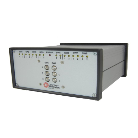
System Layout Front Panel Layout Figure 2-1 shows an example of the MMS-Model general layout, which includes: Input, output, and common connectors of all switches in the MMS configuration. Indicator LEDs for each position of each switch in the MMS configuration, and one error LED. -
Page 12: Rear Panel Layout
System Layout Rear Panel Layout Figure 2-2 shows the Mini-Matrix model rear panel general layout. All models have common parts which include: Power Entry Module 4 USB 2.0 Ports 1 Ethernet Port Figure 2-2, Mini-Matrix model Rear Panel Layout... -
Page 13: Top View Layout
System Layout Top View Layout Figure 2-3 shows the top view layout of all models. Figure 2-3, Top View of Mini-Matrix Models... -
Page 14: Rf Configuration
System Layout RF configuration Refer to appendix B. -
Page 15: Connections
Connections 3.1 Power Connection 3.1.1 Voltage The Mini-Matrix operates at a DC voltage of 12V +/- 5%. CAUTION: Operating the unit at an incorrect voltage may cause damage, possibly voiding the warranty. 3.1.2 Power Connection Perform the following steps to correctly power on the Mini-Matrix: 1. -
Page 16: Usb Port
Connections 3.2 USB Port Communication with the Mini-Matrix through one of the USB ports can be accomplished by connecting the Mini-Matrix to an RS-232 port on a PC or the USB port on a PC. Either way a few essential items will be needed. ... - Page 17 Connections 4. Open PuTTY. Under ‘Connection Type:’ select ‘Serial’. Then select the ‘Serial Line’, this is the RS232 or USB port that the user connected the Mini-Matrix to on the PC. In the example COM1 is used, but it may be different for the user.
-
Page 18: Connecting To A Usb Port
Connections 3.2.2 Connecting to a USB Port To connect the Mini-Matrix to the USB port of a PC, two USB to RS-232 cables are required. A simple USB to USB connection from the PC to the Mini-Matrix will not work. This is because both the PC and the Mini-Matrix are hosts. -
Page 19: Ethernet Port
Connections 3.3 Ethernet Port There are two ways to control the Mini-Matrix using the Ethernet port. One method is through TCP/IP (Transmission Control Protocol/Internet Protocol), which is the basic communication protocol of the internet. The second method for controlling the Mini-Matrix is using the HTTP (Hypertext Transfer Protocol) webpage. -
Page 20: Http Webpage Control
Connections 2. Then under ‘Category:’ click on ‘Terminal’. Under ‘Local echo:’ and ‘Local line editing:’ choose ‘Force On’. Then click ‘Open’ at the bottom of the PuTTY Configuration window to begin commanding and operating the Mini-Matrix. 3.3.2 HTTP Webpage Control The HTTP (Hypertext Transfer Protocol) is the user friendly way to control... -
Page 21: Connecting To A Static Ip Address
The Ethernet interface was designed to operate with common network utilities and drivers. If the Matrix fails to communicate, contact your network administrator for additional assistance. If your network administrator is unable to locate the problem, please contact Dow-Key Microwave Corporation at 1-805-650-2327. -
Page 22: Configuring The Mini-Matrix For Operation
Configuring the Mini-Matrix for Operation 4.1 Mini-Matrix Configuration The ‘brain’ inside Dow-Key Matrices, referred to as the “Mini-Matrix Controller”, has been designed to be as generic as possible in regards to how many switches it may control. Therefore, the Mini-Matrix must first be informed as to the set of switches it will control before it can operate. -
Page 23: Adding Switches
Configuring the Mini-Matrix for Operation 4.3 Adding Switches As stated in section 4.2, the switches are controlled by GPIO pins, so it is important to add switches to the correct connectors on the PCB (Printed Circuit Board). Switches must be added to the next available connector that does not share GPIO pins with another switch. -
Page 24: The Sequencer
The Sequencer 5.1 Sequencer If the user is not comfortable writing SCPI (Standard Commands for Programmable Instruments) commands, the sequencer provides an easy way to operate the Mini-Matrix. The sequencer is part of the HTTP webpage, and allows the user to designate which switch will be operated, what position will be closed, and the delay between commands. -
Page 25: Scip Command Operation
SCIP Command Operation 6.1 Introduction to SCPI SCPI is a command structure that is based on the IEEE-488.2 specification which Dow-key has adapted to work with Ethernet and USB controls. The matrix has internal software loaded that uses SCPI command structure. SCPI is the abbreviation of Standard Commands for Programmable Instruments. -
Page 26: Command Separators And Conventions
SCIP Command Operation 6.3 Command Separators and conventions A colon (:) is used to separate a command keyword from a lower level keyword. A blank space is used to separate a parameter from a command keyword. A comma (,) is used if a command requires more than one parameter. ... -
Page 27: Common Commands
SCIP Command Operation 6.4 Common Commands The following contains the IEEE 488.2 common commands of SCPI. The possible error codes assume that the correct syntax is used and, in case of a multiple command string the string is not too long. If these conditions are not met, any given command can generate these error codes: 3, 4, 30 6.4.1 *IDN? -
Page 28: Opc
SCIP Command Operation 6.4.2 *OPC? Syntax *OPC? Description This query returns an ASCII character “1” when all pending operations have been finished. Result ASCII character “1”. Possible error codes Example 1 *OPC? Result “1” Example 2 :SWIT1 4; SWIT2 4; *OPC? Result “0”... -
Page 29: Rst
SCIP Command Operation 6.4.3 *RST Syntax *RST Description This command performs a device reset. This will set the instrument so that all switches are in the default state. For SPnT switches the default state is: all RF ports are open (position 0). For the latching SPDT the default position is 1. -
Page 30: Get:dhcp
SCIP Command Operation 6.4.5 GET:DHCP Syntax GET:DHCP Description This command checks if the DHCP is enabled or not. It returns “ON” if DHCP is enabled or “OFF” if DHCP is disabled. Result “ON” if the DHCP is on “OFF” if the DHCP is off Factory default value Possible error codes... -
Page 31: System Commands
SCIP Command Operation 6.5 System Commands The following contains the SCPI system commands that are compatible with Ethernet and USB control. 6.5.1 SYST ERR? Syntax SYSTem:ERRor? Description Query the instrument’s error queue. A record of up to N errors is stored in the instrument’s error queue. - Page 32 Remote Operation Example SYST:ERR?” Result was “4, SYNTAX ERROR”, check for more errors. Description: There is a misspelling in the command or a non-numeric character was included in a command where a number should have been, or use of unrecognized symbols such as %, &, #, etc. SYST:ERR?”...
-
Page 33: Syst:serialnumber
Remote Operation 6.5.3 SYST:SERIALNUMBER? Syntax SYSTem:SERIALNUMBER? Description Returns the Mini-Matrix serial number. Result Serial Number of the Mini-Matrix Possible error codes... -
Page 34: Syst:tcpport
Remote Operation 6.5.4 SYST:TCPPORT? Syntax SYST:TCPport? Description This command will return the TCP port that is enabled for the Mini-Matrix. 10 = The default TCP port. Power on behavior Keeps last value *RST effect None Possible error codes 6.5.5 SYST:TCPPORT x Syntax SYST:TCPport x Description... -
Page 35: Syst:ipaddress
Remote Operation 6.5.6 SYST:IPADDRESS? Syntax SYSTem:IPADDRESS? Description This command will return the Mini-Matrix’s IP address. Power on behavior Keeps last value. *RST effect None Possible error codes 6.5.7 SYST:IPADDRESS xxx.yyy.zzz.aaa Syntax SYSTem:IPADDRESS xxx.yyy.zzz.aaa Description This command will set the IP address to xxx.yyy.zzz.aaa. Note: After changing the IP address, the Mini-Matrix must be power cycled for the new IP address to be implemented, and the DHCP must be turned off. -
Page 36: Syst:gateway
Remote Operation 6.5.8 SYST:GATEWAY? Syntax SYSTem:GATEWAY? Description This command will return the Mini-Matrix’s gateway address Power on behavior Keeps last value. *RST effect None Possible error codes 6.5.9 SYST:GATEWAY xxx.yyy.zzz.aaa Syntax SYSTem:GATEWAY xxx.yyy.zzz.aaa Description gateway address This command will Mini-Matrix’s xxx.yyy.zzz.aaa. -
Page 37: Syst:mask
Remote Operation 6.5.10 SYST:MASK? Syntax SYSTem:MASK? Description This command will return the mask of the Mini-Matrix. Possible Error Codes Factory default value 255.255.255.0 Power on behavior Keeps last value. *RST effect None Possible error codes 6.5.11 SYST:MASK xxx.yyy.zzz.aaa Syntax SYSTem:MASK xxx.yyy.zzz.aaa Description This command will set mask of the Mini-Matrix to xxx.yyy.zzz.aaa. -
Page 38: Syst:macaddress
Remote Operation 6.5.12 SYST:MACADDRESS? Syntax SYSTem:MACADDRESS? Description This command will return the Mini-Matrix’s MAC address in hex format. Result aa.bb.cc.dd.ee.ff Possible error codes 6.5.13 SYST:TIMEOUT? Syntax SYSTem:TIMEOUT? Description The Timeout is used to automatically close the TCP/IP socket after a certain amount of seconds of inactivity on the port. -
Page 39: Syst:timeout N
Remote Operation 6.5.14 SYST:TIMEOUT n Syntax SYSTem:TIMEOUT n Description The Timeout is used to automatically close the TCP/IP socket after a certain amount of seconds of inactivity on the port. Sets the Time out setting for the TCP/IP connection (n is in seconds). n = 0 means no Time out is set. -
Page 40: Syst:net
Remote Operation 6.5.15 SYST:NET? Syntax SYSTem:NET? Description This command will return the IP address, mask, gateway address, and MAC address. Result IPADDRESS: xxx.yyy.zzz.aaa, MASK: 255.255.255.0 GATEWAY: xxx.yyy.zzz.aaa MAC ADDRESS: aa.bb.cc.dd.ee.ff Possible error codes 6.5.16 SYST:VER? Syntax SYSTem:VER? Description This command returns the current versions of software that the Mini-Matrix is currently operating on. -
Page 41: Syst:softbuild
Remote Operation 6.5.18 SYST:SOFTBUILD? Syntax SYSTem:SOFTBUILD? Description This command returns current build of the software. Result Number of the current software build. Possible error codes 6.5.19 SYST:SOFT? Syntax SYSTem:SOFT? Description This command returns the software; version, revision, and build on the Mini- Matrix. -
Page 42: Syst:status
Remote Operation 6.5.20 SYST:STATUS? Syntax SYSTem:STATUS? Description This command will return all Switch positions and Errors list separated by a semicolon. The status response will reflect ALL items in the Mini-Matrix, while the error portion of the response is limited to the first 20 errors. Note : Multiple instances of the same error code will appear multiple times. -
Page 43: Switch [Module] Command Set
Remote Operation 6.6 Switch Command Set The following contains the switch commands of SCPI that are compatible with Ethernet and USB control. 6.6.1 :SWITch<id>[:VALue] <number> Syntax [ROUTe]:SWITch<id>[:VALue] <number> Description This command is used to control the position of the switches. The switch specified by the numeric suffix <id>... -
Page 44: Setting Switch X To Position N
Remote Operation 6.6.2 Setting Switch x to Position n x = switch address. n = position to set and must be within the switches parameter. (Example: SP6T valid positions are 0 thru 6 only). Examples: ROUTE:SWITCHx n ROUT:SWITCHx n ... -
Page 45: Requesting Switch X Current Position
Remote Operation 6.6.3 Requesting Switch x current position x = switch address. Examples: ROUTE:SWITCHx? ROUT:SWITx? :SWITCHx? :SWITx? Result: Returns the current position of switch x. Possible error codes 10, 11, 12, 13 Timing The timing to execute a command depends on the length of the command (in case of concatenated commands). -
Page 46: Route:count
Remote Operation 6.6.4 ROUTE:COUNT? Syntax ROUTe:COUNT? :COUNT? Description This command returns how many total cycles the switches have completed. The total count is defined as the sum of the cycles of all positions combined. This returns a value for every switch in the configuration. Result Switx n;... -
Page 47: Route:countx N
Remote Operation 6.6.6 ROUTE:COUNTx n? x = switch address. n = position of the switch. Syntax ROUTe:COUNTx n? :COUNTx n? Description This command counts how many times switch ‘x’ has cycled to position ‘n’, where ‘x’ is the address of the switch and ‘n’ is the position of the switch. This will give the user how many times only a single position has been cycled. - Page 48 Remote Operation This page intentionally left blank...
- Page 49 TCP/IP, HTTP, and USB Command Descriptions for ‘MMS’ Matrices Command Syntax Response /HTTP Returns string in ’Model Name’ in the configuration file (or equivalent of config. file). As a minimum will have model name. √ √ *IDN? Matrix model Could also have: Vendor, model, serial number, software revision (The response shown in this table is just an example).
- Page 51 Remote Operation Note: 1. Commands are NOT case sensitive. 2. Every command and response on the serial or USB port shall have “\r\n” Carriage return (0x0D) and Line Feed (0x0A) at the end. 3. Multiple commands with same header can be given in a single command line. (See rule # 5 for an exception to this).
-
Page 52: Web Page Server (Http)
Mini-Matrix. If the IP address has been changed use the current IP address to access the HTTP page. The following page should appear: ‘Status’, ‘Control’, or ‘Sequencer’ may be selected. ‘Configuration’ is password protected, and reserved for the sole use by Dow-Key Microwave. -
Page 53: Matrix Status
Web Page Server 7.2 Matrix Status Clicking on ‘Matrix Status’ will show the page below. This page shows the configuration and the positions of the switches. There is an ‘Error’ button on the page as well. This button will be green as long as there are not any errors. -
Page 54: Matrix Control
Web Page Server 7.3 Matrix Control Clicking on ‘Matrix control’ will show the page below. SCPI commands may be typed into the ‘Command:’ text box and then by clicking the ‘Send’ button the command will be executed. See Section 6 for the SCPI command list and its syntax. -
Page 55: Mini-Matrix Configuration
Web Page Server 7.4 Mini-Matrix Configuration Clicking on the “Matrix Configuration” will show the page below. The Mini-Matrix configuration page allows for easy configuration of the Mini- Matrix by Dow-Key. The ‘Matrix Configuration’ page is password protected so the configuration isn’t changed accidentally. Username: dowkey Password: 123 There are a maximum of eight switches that can be connected to the Mini-Matrix... -
Page 56: The Sequencer
Web Page Server 7.5 The Sequencer Clicking on “Sequencer” will show the page below. The sequencer allows for many commands (steps) to be implemented, and exectued in sequential order. The user has control over each switch, the position of each switch, and the delay in milliseconds (minimum 50ms) between each command (step). -
Page 57: The Log
Web Page Server 7.6 The Log Clicking on ‘View Log’ will show the page below. The ‘Log’ page records which switches are commanded, the switches position, and the delay. This helps the user debug the system and will output an error if one is deteced. This is especially useful when looping the sequencer and the user can not tell when or where the error occurred. -
Page 58: Technical Specifications
Appendix A Technical Specifications Model: MMS-Series Configuration: Up to eight latching SPDT switches mounted on the front panel Up to two latching SP6T switches mounted on the front panel RF Connectors: SMA (on front panel) Frequency range: DC to 26.5 GHz SPDT RF Characteristics (R521K-420853A &... -
Page 59: Rf Configuration
Appendix B RF Configuration Terminated SPDT (TSPDT) Configurations Model: Mini-Matrix (MMS-A26S-2TSPDT) Two TSPDT (terminated) switches (Dow-Key part number: R521K-420853A) mounted on the front. Model: Mini-Matrix (MMS-A26S-4TSPDT) Four TSPDT (terminated) switches (Dow-Key part number: R521K-420853A) mounted on the front. Model: Mini-Matrix (MMS-A26S-6TSPDT) Six TSPDT (terminated) switches (Dow-Key part number: R521K-420853A) mounted on the front. -
Page 60: Terminated Sp6T (Tsp6T) Configurations
Appendix B Terminated SP6T (TSP6T) Configurations Model: Mini-Matrix (MMS-A26S-1TSP6T) One TSP6T (terminated) switch (Dow-Key part number: R461JK-420853A) on the front. Model: Mini-Matrix (MMS-A26S-2TSP6T) Two TSP6T (terminated) switches (Dow-Key part number: R461JK-420853A) on the front. Terminated SP6T (TSP6T) + Terminated SPDT (TSPDT) Configurations Model: Mini-Matrix (MMS-A26S-1TSP6T+2TSPDT) One TSP6T (terminated) switch (Dow-Key part number: R461JK-420853A) and two TSPDT (terminated) (Dow-Key part number: R521K-420853A) on the front. -
Page 61: Mini-Matrix Rf Diagram
Appendix B Mini-Matrix RF diagram Note: The switches are bi-directional. Hence each RF port can be considered an input or an output. Below are two examples of RF block diagrams of: - Two independent SPDT (or TSPDT) switches. - One independent SP6T switch. Matrix p.n.
Need help?
Do you have a question about the MMS Mini-Matrix and is the answer not in the manual?
Questions and answers