Table of Contents
Advertisement
Quick Links
Advertisement
Table of Contents

Summary of Contents for Teledyne Cetac Technologies SPM-700
- Page 1 SPM-700 Syringe Pump Module Installation Guide Manual Part Number 610108 Rev 0...
- Page 2 COPYRIGHT TRADEMARK ACKNOWLEDGEMENTS © 2018 Teledyne CETAC Technologies Windows is a registered trademark of Microsoft Corporation in the United States and 610108 Rev 0 , December, 2018 other countries. Teledyne CETAC Technologies authorizes its PharMed and Tygon are registered customers to reproduce, transmit, or store...
-
Page 3: Table Of Contents
Contents Introduction ......................4 Overview............................ 4 Chemical Compatibility ....................... 4 Operator Qualifications ....................... 5 Choosing a Location for Installation ................5 Proximity to the Instrumentation ................5 Space Requirements ...................... 6 Power Requirements..................... 6 Unpacking the Syringe Pump Module ................6 Installing the Syringe Module ................ -
Page 4: Introduction
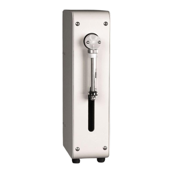
1 Introduction Overview Power Switch Valve with Input and Output Ports Syringe Serial Port USB Port Plunger RS-485 Ports Thumbscrew Power Connector 1-1 Front and Back Views. IGURE The color and branding of the module may vary from what is shown here. Chemical Compatibility The syringe module is intended for use with sample matrices with the following characteristics:... -
Page 5: Operator Qualifications
used at temperatures less than 135°C, they can withstand repeated exposure to the following substances: Predominantly aqueous solutions of acids (less than 10%), including HNO and HCl. Predominantly aqueous solutions of strong bases (less than 10%) Common organic solvents such as acetone, alcohols, ethyl acetate, Methylethylketone (MEK), petroleum oils and derived fuels, tetrachloroethylene, toluene, kerosene and xylene. -
Page 6: Space Requirements
Space Requirements You will need easy access to the back of the syringe module to reach the power switch. As a minimum, allow at least 5 cm behind the syringe module for cable egress, ventilation, and access to the power switch. Always position the equipment so that it is easy to disconnect the power cord. -
Page 7: Installing The Syringe Module
2 Installing the Syringe Module The syringe pump module may be placed on the workbench, or it can be attached to the autosampler using an optional mounting block. Installing the Accessory Module Mounting Blocks The syringe pump module can be mounted on an accessory mounting block, and the mounting block can be installed on either side of the autosampler. - Page 8 Syringe Pump Module Installation Guide Chapter 2: Installing the Syringe Module Check that the black pin is in the position toward the front of the autosampler. If necessary, turn the block over and move the pin to the other hole. Front Back 2-2 Position of Pin on Mounting Block (Bottom View).
-
Page 9: Mounting The Syringe Pump Modules
Syringe Pump Module Installation Guide Chapter 2: Installing the Syringe Module Mounting the Syringe Pump Modules Place the syringe pump on the mounting block. The black pin on the block fits into the hole on the underside of the module. Push the module back until the front is flush with the front of the autosampler. -
Page 10: Connecting The Tubing
Syringe Pump Module Installation Guide Chapter 2: Installing the Syringe Module Connecting the Tubing Tighten the fittings using only your fingers. Turn the fittings slowly at first, NOTICE making sure they are not cross-threaded. Using excessive force will damage both the fittings and the valve. The direction of liquid flow through the valve at the top of the syringe is set by software. -
Page 11: Connecting The Power Supply
Syringe Pump Module Installation Guide Chapter 2: Installing the Syringe Module Connecting the Power Supply It is important to use the appropriate power cord for your country. Use only the provided power supply. The syringe pump module is typically powered by a desktop transformer, although some configurations may be powered by another kind of power supply. -
Page 12: Connecting The Syringe Module Directly To The Host Pc
Syringe Pump Module Installation Guide Chapter 2: Installing the Syringe Module Connecting the Syringe Module Directly to the Host PC The syringe pump module may be controlled by a direct connection to a host PC. The syringe pump module supports the following communications protocols: ... -
Page 13: Connecting A Serial Cable
Syringe Pump Module Installation Guide Chapter 2: Installing the Syringe Module When driver installation is complete, make a note of which COM port number was assigned. The COM port number may be displayed in a “bubble” in the lower right corner of the screen. Confirm that the COM port selected for the USB matches the port selected in the host computer's instrument control software. -
Page 14: Starting The Pump
Syringe Pump Module Installation Guide Chapter 2: Installing the Syringe Module Remove the plunger thumbscrew at the base of the syringe plunger. 2-10 Removing the Syringe Thumbscrew IGURE If you are replacing a syringe, carefully unscrew the syringe barrel (about 1 1/2 turns) while pulling downward slightly. -
Page 15: Shutting Down The Pump
Syringe Pump Module Installation Guide Chapter 2: Installing the Syringe Module Shutting Down the Pump Turn the power switch on the syringe pump module OFF. If the power supply is equipped with a power switch, turn it OFF. If you will be performing maintenance, unplug the power cord either at the power supply or at the wall outlet. -
Page 16: Maintaining And Troubleshooting The Product
3 Maintaining and Troubleshooting the Product Cleaning the Syringe Module It is important to clean up spills and remove contaminants, such as abrasives, from the moving parts. It may also be necessary to chemically neutralize spills. Shut down and unplug the autosampler and syringe module. Wipe the exterior surfaces using a towel dampened with a lab-grade cleaning agent. - Page 17 IGURE Inspect the seal and replace it if it is worn, cracked, or damaged. (For replacement parts, contact Teledyne CETAC Technologies. See page 2 for contact information.) Wipe the inside of the syringe barrel, the plunger, and the seal using a lint-free laboratory wiper or paper towel.
-
Page 18: Returning The Product To Cetac For Service
Do not return products which are contaminated by radioactive materials, infectious agents, or other materials constituting health hazards to CETAC employees. Product Warranty Statement NOTE Contact Teledyne CETAC Technologies or refer to the warranty card which came with your product for the exact terms of your warranty. -
Page 19: Safety And Regulatory Information
Syringe Pump Module Installation Guide Chapter 4: Safety and Regulatory Information 4 Safety and Regulatory Information Review this product and related documentation to familiarize with safety markings and instructions before you operate the instrument. Safety Characteristics Environmental Characteristics These environmental characteristics indicate the conditions for safe operation in accordance with IEC/EN-61010-1:2010. -
Page 20: Electrical Characteristics
The power cord set supplied with your instrument meets the requirements of the country where you will use the instrument. If you need a different power cord, contact Teledyne CETAC Technologies. The operator should check the power supply cord condition. The equipment should not be operated if the power connector is cracked or broken. -
Page 21: Mains Disconnect
Syringe Pump Module Installation Guide Chapter 4: Safety and Regulatory Information personnel for loose or damaged parts. See individual parts lists for approved replacement parts. Mains Disconnect The power switch on the rear panel is not the mains disconnect. Power mains disconnect is accomplished by unplugging the power cord at the instrument or at the wall outlet. -
Page 22: Explanation Of Caution And Warning Notices
Syringe Pump Module Installation Guide EXPLOSION HAZARD WARNING Do not operate in an explosive atmosphere. Do not operate in the presence of chemical vapors with a flashpoint lower than 200 °C. CHEMICAL HAZARDS Learn about the chemicals which will be used in and near the instrument, WARNING and observe the necessary precautions. -
Page 23: Explanation Of Regulatory Marks
Chapter 4: Safety and Regulatory Information The FCC requires the user to be notified that any changes or modifications made to this device that are not expressly approved by Teledyne CETAC Technologies may void the user's authority to operate the equipment.
Need help?
Do you have a question about the SPM-700 and is the answer not in the manual?
Questions and answers