Table of Contents
Advertisement
Quick Links
Advertisement
Table of Contents

Related Manuals for Applied Research and Technology SMS226

Summary of Contents for Applied Research and Technology SMS226
- Page 1 SMS226 Automated Speaker Management System USER’S GUIDE...
- Page 2 IMPORTANT SAFETY INSTRUCTIONS – READ FIRST This symbol, wherever it appears, This symbol, wherever it appears, alerts alerts you to the presence of uninsulated you to important operating and maintenance dangerous voltage inside the enclosure. Voltage instructions in the accompanying literature. that may be sufficient to constitute a risk of shock.
-
Page 3: Table Of Contents
SMS226 Speaker Management System IMPORTANT SAFETY INSTRUCTIONS – READ FIRST ..................II INTRODUCTION ............................... 1 SMS226 features ....................................... 2 INSTALLATION ..............................3 AC Power Hookup ......................................3 Analog Audio Connections ....................................3 USB connection ......................................... 3 BASIC OPERATION ............................4 User interface controls ....................................... -
Page 4: Introduction
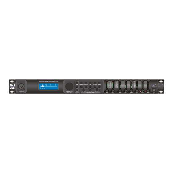
INTRODUCTION The ART SMS226 is a two input, six output speaker management system with a number of advanced functions and easy setup. The unit combines mono or stereo processing, a flexible crossover with speaker protection and an automated setup facility. A graphic LCD display and LED meters allow control and monitoring of the SMS226. -
Page 5: Sms226 Features
SMS226 features 2 inputs, 6 outputs plus a measurement mic input Configurable for 2x2, 2x3, 2x2+1, 1x4, 1x5 and 1x6 Simple user interface supported with Graphics LCD, encoder and quick access menu buttons Three setup wizards (Auto-feedback, Auto-EQ, System configuration) ... -
Page 6: Installation
AC Power Hookup The ART SMS226 has a high efficiency universal power supply. Connect the unit to mains power of the type marked on the rear panel. The power source must provide a good ground connection, and the ground pin on the mains plug should never be defeated. -
Page 7: Basic Operation
BASIC OPERATION User interface controls The SMS226 is controlled from the front panel by a rotary encoder and a number of switches. The switches allow quick access to various functions. Pushing (also referred to as "clicking") the encoder knob will generally switch between a value or a parameter adjustment. -
Page 8: Configuration Wizards
"Loading Please Wait" message appears in the LCD display while the unit works to retrieve the info. When the SMS226 is fully configured, you have the option of running the Auto-EQ wizard by clicking on the Next parameter, or Exiting. -
Page 9: Auto-Feedback Button
After the parameters are set, select Next and push the encoder to proceed to the initial menu. Selecting Run from the initial screen will drop you to the Level adjustment menu. The Back function is now available in subsequent sub-menus. This will allow you to return to previous menus to make adjustments. Push the encoder and adjust the level. -
Page 10: System Functions
FIGURE 2 – Signal Flow Block Diagram SYSTEM FUNCTIONS STORE button The Store function consists of setting the destination and name of the preset and additionally the source if the Type is set to Speaker or Power Amp. You can store up to 20 System presets (numbered 11 to 30) or 20 User Speaker or Power Amp presets (numbered 201 to 220). -
Page 11: Recall Button
~559 ft). You can use this to align clusters when using the unit in a 2 x 2 or 2 x 3 configuration. You can also align clusters with multiple SMS226's through this delay adjustment. When the display reads "Delay A>" you... -
Page 12: System Menu
(default) prevents uninitiated users from accidentally adjusting the volume. Pink Noise Level The SMS226 has a built in Pink Noise generator used for system testing. This parameter allows level adjustment before this source is selected to prevent system damage from excessive testing volume. -
Page 13: Security Menu
SMS226 access is prevented when the Device parameter is set to Locked. New Password The new password replaces the old password after the Device parameter is set to Locked. The SMS226 does not compensate for altitude, barometric pressure and temperature so the measured delay may vary by a few percent. -
Page 14: Input Module Descriptions
INPUT MODULE DESCRIPTIONS General settings The SMS226 architecture consists of two inputs that can be operated in dual or stereo mode. Stereo input operation is simplified by setting the Input Link ON (under the UTILITY/System menu). When linked, both channels' parameters are identical as well as compressor attenuation. - Page 15 The Type parameter allows you to tailor the feedback suppressor's action for the audio's spectral content. Sometimes the room characteristics change due to temperature, humidity or even the size of the crowd present. Since even the active filters remain fixed (depending on the Lift Live parameter setting), you may need to reset the notch filters.
-
Page 16: Output Module Descriptions
OUTPUT MODULE DESCRIPTIONS Output button The output parameters allow adjustment of the unique Name (up to 6 characters), Routing source, level control, phase and meter operation. The Routing parameter (under the Output button) can be set to In A, In B or In A+B. Setting this parameter independently on each output allows you to avoid re-patching the outputs (i.e. - Page 17 show that you have exceeded the threshold level and the limiter is just beginning to reduce gain. You can tie the gain of one limiter to another using the Link function. Refer to the System Functions section on Link Modes for information on how to tie limiters' gains together to maintain the stereo image between adjacent channels or maintain spectral balance (by linking all limiters together).
-
Page 18: Pc Interface
PC INTERFACE Overview The PC software provides an easier, graphics based interface for the SMS226. You have access to either input, output or system overview pages allowing quicker access to all of the adjustable parameters as well as a higher resolution frequency response graph. The PC software adds a graph for the threshold characteristics of the compressor and limiters as well. -
Page 19: Usb Connection
Make sure that the SMS226 (as well as your computer) is powered ON and then connect to your computer using a "B" type connector on the front panel of the SMS226. You can use a USB 1.1 or USB 2.0 connection. -
Page 20: Operation
Unique to this mode are the Save to PC and Load from PC buttons. These functions store or recall the entire memory of the SMS226 to/from your PC. (The Store and Recall buttons merely save or load a single system snapshot in one of the memory locations inside the unit.) The Overview tab The Overview tab is used to see and adjust system parameters. -
Page 21: Figure 5 - Pc Inputs Screen
The Input tabs The Input tab allows access to all of the processes related to the input audio before it is routed to the outputs. This page replaces the entire upper row of buttons on the main unit (Compressor, Graphic EQ, Gate, Sub- synth, Feedback). -
Page 22: Figure 6 - Pc Outputs Screen
The Output tabs Each output tab allows access to all of the processes related to the corresponding output. This page replaces the entire middle row of buttons on the main unit Crossover, Parametric EQ, Delay, Limiter, Output). Refer to the operation of these functions in the OUTPUT MODULE DESCRIPTIONS section. -
Page 23: Warranty Information
WARRANTY INFORMATION Limited Warranty: Applied Research and Technology will provide warranty and service for this unit in accordance with the following warrants: Applied Research and Technology, (A R T) warrants to the original purchaser that this product and the components thereof will be free from defects in workmanship and materials for a period of three years from the date of purchase. -
Page 24: Service
SERVICE: The following information is provided in the unlikely event that your unit requires service. 1) Be sure that the unit is the cause of the problem. Check to make sure the unit has power, all cables are connected correctly, and the cables themselves are in working condition. You may want to consult with your dealer for assistance in troubleshooting or testing your particular configuration. -
Page 25: Specifications
SPECIFICATIONS Input Impedance 3.4k Ohms ......................Input A, Input B ................10k Ohms ..................< 0.005% @1kHz Maximum Input ..............+20dBu Maximum Output ..............+20dBu balanced Bandwidth ................10-20kHz +1dB Dimensions 3.50” H x 19.0” W x 9.17” D (88.9mm H x 482.6mm W x 232.9mm D) .................. - Page 26 NOTES...
- Page 28 www.artproaudio.com E-mail: support@artproaudio.com © 2014 Applied Research & Technology 226-5001-101...
Need help?
Do you have a question about the SMS226 and is the answer not in the manual?
Questions and answers