
Subscribe to Our Youtube Channel
Summary of Contents for Energetiq EQ-99X LDLS
- Page 1 Model EQ-99X ™ LDLS Laser-Driven Light Source Operation and Maintenance Manual Revision 2 September 30, 2015 Part Number DOC-6521...
- Page 2 Energetiq and shall not be reproduced in whole or in part without the written consent of Energetiq. The content of this manual is subject to change without notice.
- Page 3 Declaration of Conformity We, the manufacturers Energetiq Technology Inc. 7 Constitution Way Woburn, Massachusetts 01801 USA hereby declare that the product family LDLS Laser-Driven Light Source ™ Model EQ-9X Series High Brightness Broadband Light Source is in conformity with the requirements of the following standards...
-
Page 5: Table Of Contents
Table of Contents Chapter 1 ..........................1 General Information ....................1 Safety ............................... 1 Chapter 2 ..........................8 Description ........................8 General ............................8 System Description ........................11 Power Supply Controller ......................12 Lamp House ..........................13 Chapter 3 ..........................16 Installation........................ -
Page 7: Chapter 1
Chapter 1 GENERAL INFORMATION Safety WARNING This unit emits ultraviolet (UV) radiation that is harmful to humans. Avoid exposure to the direct or reflected output beam. Make certain that the appropriate output beam shields and optics are in place prior to energizing the unit. All interlocks must be satisfied prior to operation;... - Page 8 Other than a bulb replacement, there are no user-serviceable parts inside the EQ-99X. For any problems encountered during operation, please contact Energetiq Technology for assistance. If there is a component failure, do not attempt to open the Power Supply Controller or Lamp House enclosure of the EQ-99X.
- Page 9 The EQ-99X utilizes a quartz lamp containing a high-pressure gas fill. Explosion of the lamp and possible injury from flying fragments can occur if the lamp is mishandled. Do not open the enclosure of either the Lamp House enclosure or the Power Supply Controller.
- Page 10 Lamp House or Power Supply Controller enclosure. The unit must not be operated if the covers are removed or it is defective in any way. Contact Energetiq if any problems with the equipment are suspected. EQ-99X Operation Manual Rev. 2...
- Page 11 Labels and Safety Notification The following safety labels appear on the product. Figure 1 shows the location of each label on the EQ-99X system. UV Hazard warning label – indicates hazardous levels of UV light are present. Manufacturer’s identification label – gives the manufacturer’s name and address, and the model, serial number, and date of manufacture of the equipment.
- Page 12 Figure 1: Safety Label Locations Non-interlocked Housing Label Manufacturer’s Certification Explanatory Label Label Identification label Non-interlocked Housing Label Manufacturer’s Identification label Safety Interlocks The EQ-99X is equipped with interlocks to prevent operation of the device when any of the following conditions are present: 1.
- Page 13 EQ-99X Operation Manual Rev. 2...
-
Page 14: Chapter 2
Chapter 2 DESCRIPTION General The EQ-99X is a broad-band lamp system for use in a wide variety of applications. The lamp produces high brightness, broad-band light from DUV wavelengths through visible and beyond. The output is very stable, and has a long lifetime before any service is required. A simple control interface ensures ease of use. - Page 15 Specifications Optical Performance Typical output spectrum: see Figure 2. EQ-99 D2 Lamp 0.01 0.001 Wavelength, nm Figure 2: Typical Output Spectrum Physical Specifications Dimensions (H x W x D) Lamp House: 82 x 86 x 76 mm (3.2 x 3.4 x 3.0 in) ...
- Page 16 Utility Requirements Electrical: 12VDC, 140W Cooling: natural convection and internal fan, no auxiliary cooling necessary Purge gas (optional): clean dry nitrogen, filtered to 5um 20 psig (0.14 MPa) supply pressure Remote Interface Digital Inputs Type: Optocoupler LED ...
-
Page 17: System Description
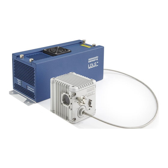
System Description As shown in Figure 3 the EQ-99X system consists of a Power Supply Controller unit, Lamp House, laser fiber optic cable, and Lamp House signal cable (not shown). Power and I/O interface connections (also not shown) are provided by the user. The following sections provide descriptions of the system components and controls, and gives an overview of their functions. -
Page 18: Power Supply Controller
Power Supply Controller The Power Supply Controller contains: IR Diode Laser Laser power supply Thermo-electric cooler for laser Permanently attached, armored laser fiber optic cable Control electronics Status indicator LEDs Interface connectors External features (refer to Figure 3): Status Indicator LEDs These five LEDs indicate the system status. -
Page 19: Lamp House
Provides access to control and status signals. See Chapter 3 for pin assignments and functions. This is the only operator interface to the EQ-99X – there are no local controls. Energetiq offers the EQ-99-RC Remote Control Module which connects to the Input/Output connector and provides a means of local control. - Page 20 Interface connectors Purge Gas Port Signal Connector (to Controller) Laser ON Indicator Lamp Window Bulb mounting flange Laser Input (SMA-type) Figure 4: Lamp House Assembly External features (refer to Figure 4): Lamp Window The lamp window at the optical output provides protection from the high pressure bulb inside the Lamp House.
- Page 21 Nitrogen Purge Inlet This is the inlet fitting for nitrogen purge gas. Purge gas is optional but is recommended for best performance. With no purge, ozone will form from atmospheric oxygen and attenuate the light output in the 220 – 280nm band. In addition, atmospheric oxygen and water vapor will attenuate the output below 200nm.
-
Page 22: Chapter 3
Use care when unpacking to avoid damaging the armored fiber optic cable. If any part is missing or appears damaged, contact Energetiq immediately. Do not attempt to substitute any parts. There are no user-serviceable parts inside the EQ-99X Lamp House or Power Supply Controller unit. - Page 23 on the EQ-99X is a latching connector. Once fully inserted, the connector will not release unless the body of the connector is pulled first. This protects from accidental removal of power if the power cable is pulled. Connect to a 12VDC source as follows: Connector Kycon KPPX-4P Pins 3 &...
- Page 24 Figure 5: Lamp House mechanical layout EQ-99X Operation Manual Rev. 2...
- Page 25 EQ-99X Operation Manual Rev. 2...
- Page 26 Signal Connections The EQ-99X is controlled through the remote I/O connector. Table 3 gives the pin assignments and functions for this interface. Connect to the user’s control system using a suitable cable. Mating connector is a standard high-density 15-pin d- sub male (for example, Amp part no.
- Page 27 5V Power Pin 5 Isolated 0.1uF 5VDC supply Contact or Inputs solid-state switch Pins 11, 12, 13 0.1uF Outputs Load Pins 1, 2, 3, 4 5V Return Pins 6, 7, 8, 9 5V Power Pin 5 Isolated 0.1uF 5VDC supply Contact or Inputs solid-state switch...
-
Page 28: Installation Procedure
This is done to minimize the possibility of debris or particles contaminating the end of the laser fiber. Energetiq strongly recommends leaving the laser fiber connected, unless it is necessary to disconnect it for installation or routing of the laser fiber. If the laser fiber must be disconnected, apply SMA caps immediately to both ends, and follow directions on inspection and cleaning of the laser fiber described in Chapter 5. -
Page 29: Water Cooling Installation For Eq-99-Cal
9. Alternately, if using the EQ-99-RC Remote Control Module, place it on a clean rigid surface. Install the supplied 15-pin cable from the Power Supply Controller to the EQ-99-RC. 10. Connect 12VDC input power source to the Power Supply Controller. The system is now ready to operate. - Page 30 The procedure below will explain the proper steps to appropriately assemble the water cooling components of the EQ-99-CAL unit. 1. The Swagelok fittings will need to be attached to the two copper tubing, as shown in Figure 9. a. The ¼” end of the fitting will mate to the copper tubing. b.
-
Page 31: Chapter 4
This is very unusual. However, if this occurs, turn the OPERATE switch to the OFF position (down) and begin at Step 1 again. If this occurs multiple times, contact Energetiq service Stopping To turn the LAMP off, simply turn the OPERATE Switch to the OFF position. If the lamp will not be used for some time, the 12VDC supply can be turned off. - Page 32 To minimize wear on the ignition components, it is best to avoid frequently starting and stopping the lamp. It is recommended to run the lamp continuously rather than turn the lamp off and on several times in a day. EQ-99X Operation Manual Rev. 2...
-
Page 33: Chapter 5
Fiber Cleaning Basics: The LDLS laser fiber connector is carefully inspected and is clean prior to shipment. Energetiq strongly recommends leaving the laser fiber connected, unless necessary for installation or routing of the laser fiber. Operating the LDLS with a contaminated fiber introduces the risk of decreased performance or damage to the unit. - Page 34 Fiber Inspection and Cleaning Process CAUTION Disconnect power from the EQ-99 Power Supply Controller unit before performing fiber inspection. Start Inspect Fiber Inspect Blow off Ferrule Inspect Fiber Fiber end and Nut threads with N2 or CDA Clean Fiber Lint Blow Clean Fiber •...
- Page 35 Westover Digital inspection scopes. This custom adapter allows the scope to be used with the EQ-99 laser fiber and integral interlock ring. The custom adapter may not be compatible with other fiber inspection equipment. The following fiber inspection equipment can be purchased from Energetiq: Energetiq Part Number Description...
- Page 36 Examples of Fiber Images Figure 13: Fiber End Images Fiber Cladding Fiber Core Area Fiber Cleaning Tools 1. Clean Dry Air or Pressurized Nitrogen 2. Dust Off (or similar clean, compressed air) 3. Cletop (www.cletop.com) 4. Lint Free Wipe with Isopropyl Alcohol Figure 11.
-
Page 37: Troubleshooting
Troubleshooting Fault Indicator Block Diagram: Laser On Lamp Fault Controller Fault De-Asserted 150 sec Lamp On after Operate Asserted Asserted De-Asserted Command (pin 3 on remote) (pin 4 on remote) (pin 1 on remote) (pin 2 on remote) Signal Available on User Interface Internal Logic That Generates Signal External Control Cable Not... -
Page 38: Lamp Replacement
If all of the interlocks are OK and either the lamp or controller interlock faults will not clear, please contact the factory. Condition: Lamp fails to ignite after several tries. Action Contact Energetiq. Lamp Replacement Contact Energetiq if a bad lamp is suspected. EQ-99X Operation Manual Rev. 2... - Page 39 Energetiq and shall not be reproduced in whole or in part without the written consent of Energetiq. The content of this manual is subject to change without notice.
Need help?
Do you have a question about the EQ-99X LDLS and is the answer not in the manual?
Questions and answers